This section allows the creation and maintenance of the inventory parts in Progress Plus.
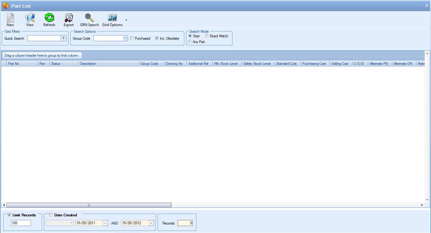
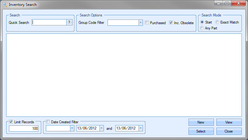
The filters at the top of the screen allow the user to search and display all parts based on the search criteria entered.

The Quick Search option allows the user to enter a piece of text to search for. This can be a specific part number, part of a part number or description, drawing number, etc. Progress will search for all instances of this text based on the Search Mode selected and present a list of all parts which meet the search criteria.
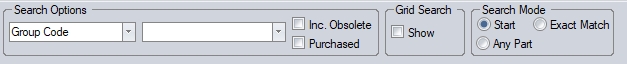
There are three Search Modes available:
| START | This will display all parts where the search text is at the start of a field text. |
| EXACT MATCH | This will display all parts where a field text matches exactly the search text entered. |
| ANY PART | This will display all parts where the field text contains the search text at any point. |
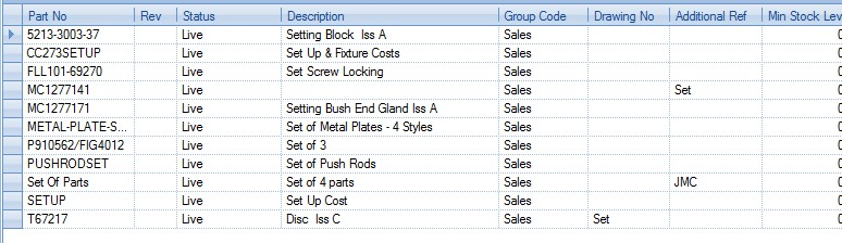
(Example #1: Searching for “set” with a Search Mode of “START”)

(Example #2: Searching for “set” with a Search Mode of “EXACT MATCH”)
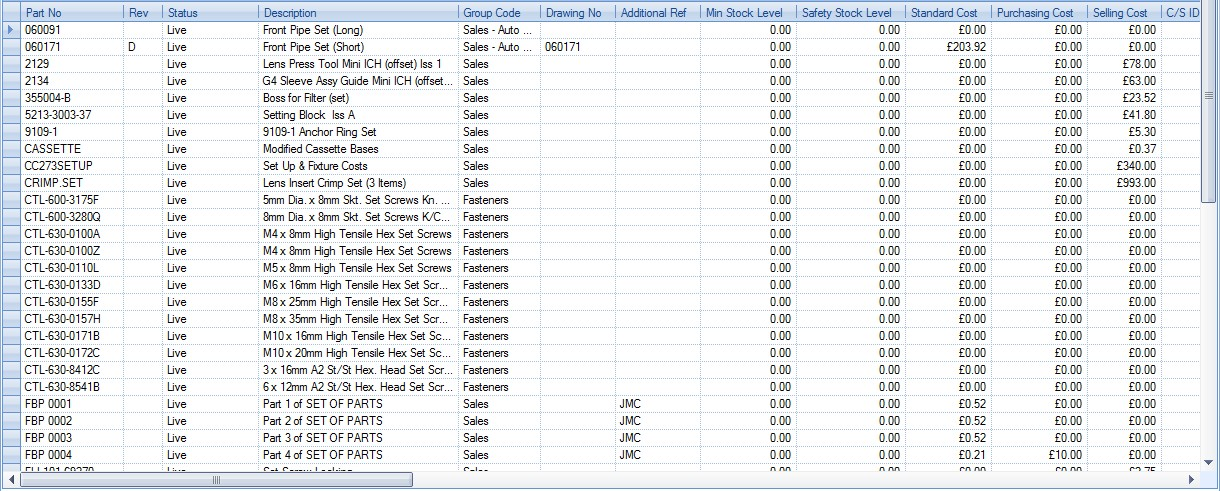
(Example #3: Searching for “set” with a Search Mode of “ANY PART”)
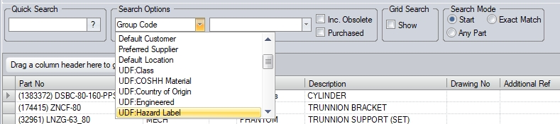
The user also has option to filter the parts list by specific fields, including user defined fields, and also options for including obsolete parts, or for restricting the search to only purchased parts.
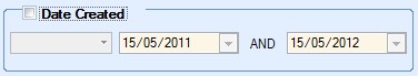
In addition to the filter options above, the user can also filter the parts list by the creation date of the part itself using the date filter at the bottom of the screen.
The user can also set the maximum number of part records to be displayed on the grid using the LIMIT RECORDS option.
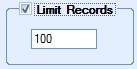
The default value of this option is set in the system options and is useful when large amounts of data are held in Progress as this limits the amount of data being displayed. The limit can be removed by the user if necessary by simply unticking the option, or they can simply increase the limit quantity to a more suitable value. The number of parts shown in the grid is also summarised at the bottom of the screen. This gives a total count of the parts shown.

If any filters have been specified, the user can click the REFRESH option at the top of the screen or the user can click on the ![]() option at the end of the Quick Search field to update the part list based on the filters chosen.
option at the end of the Quick Search field to update the part list based on the filters chosen.
View
The user can view the details of any selected part record by highlighting the part required in the grid and clicking the View option above. Alternatively, the user can view the details of a part record by double-clicking on the required part directly on the grid. Either method will present the user with the following screen.
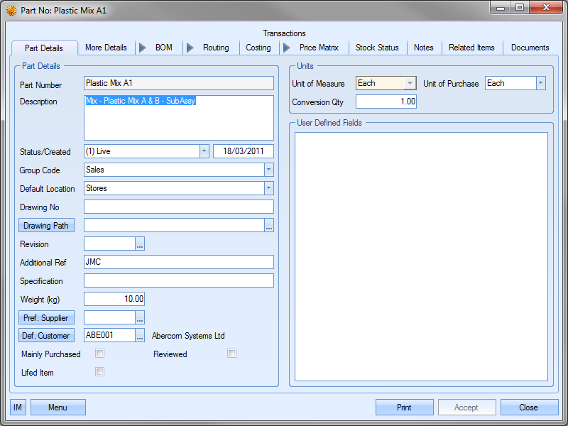
The user can now view or amend the details of the selected part as required. Clicking ACCEPT will save any changes made.
NOTE: The Part Number and the Unit of Measure (UoM) fields cannot be changed once the part has been created. If either of these fields has been entered incorrectly, the user must change the part status to an "obsolete" status and create a new part number.
Export
This option allows the user to export out the details of the parts listed on the grid to a spreadsheet. The export spreadsheet can contain one (individual options) or more elements of the selected parts.
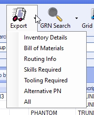
If the user selects the ALL option, the spreadsheet generated will contain the part details as well as all other information associated with the parts. Selecting any other option will generate a spreadsheet with just the selected details of the parts.
The contents of the spreadsheet is based on the list of parts currently displayed on the Parts List screen. The user can use the filter option on the Parts List screen to identify the parts they are interested in and then choose the required Export option.
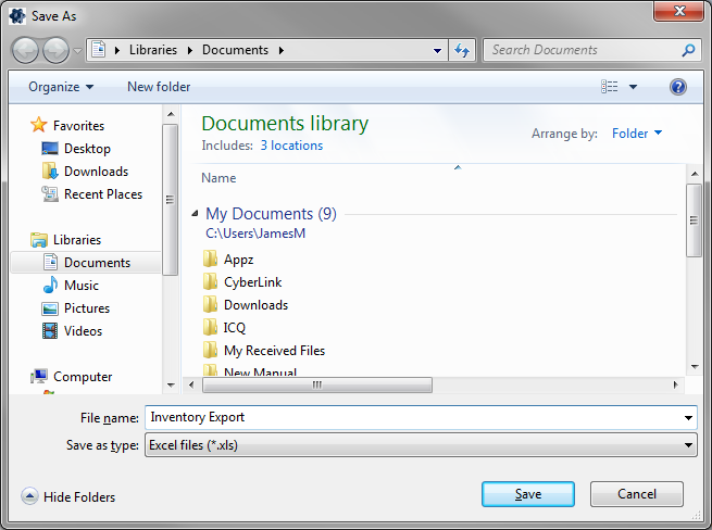
Once the spreadsheet is generated, it will open in Excel. The spreadsheet contains the sheet(s) of information, each labelled according to the information they contain.
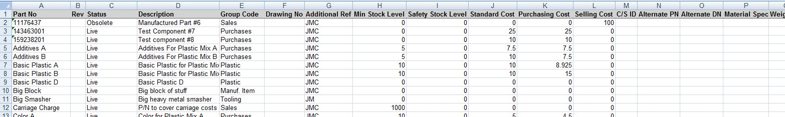
(Example INVENTORY DETAILS sheet)
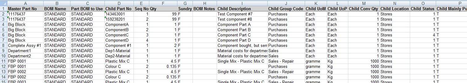
(Example BILL OF MATERIALS sheet)
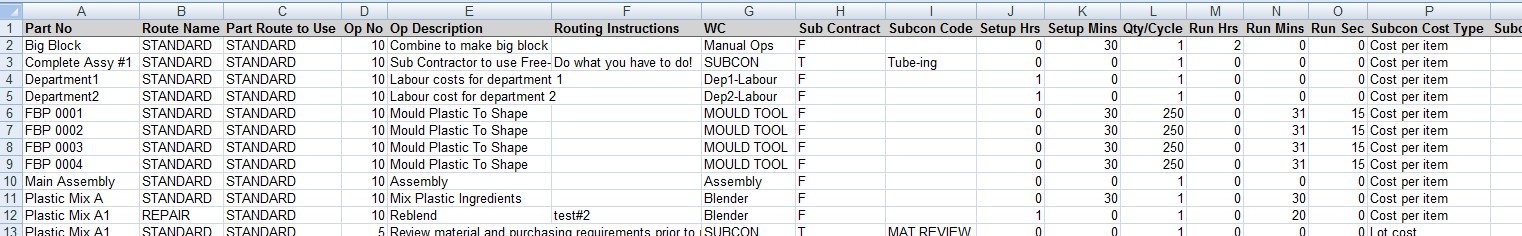
(Example ROUTING INFO sheet)
NOTE: The spreadsheet produced is generated using the templates required for the import processes associated with inventory parts, BOMs and routings. These sheets contain all the columns, column names and specific sheet names required for the Import process of inventory parts and the BOM or routing information associated with these parts. Any changes to the templates WILL result in issues when trying to import information to Progress using the modified sheets.
For more information on importing part information into Progress, please refer to the Tools section of this manual.
GRN Search
This option allows the user to search for specific receipts or issues, as well as edit these records if required. For more information on these options, please refer to the GRNs (Receipts and Issues) section of the manual.
Parts - Creating New
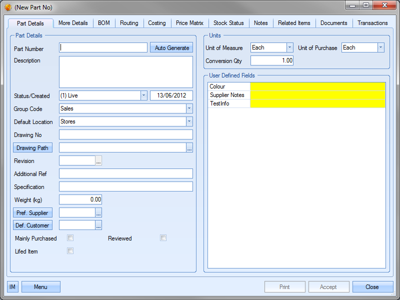
The NEW option allows the user to create new parts in Progress. Clicking this option will present the user with the New Part No screen.
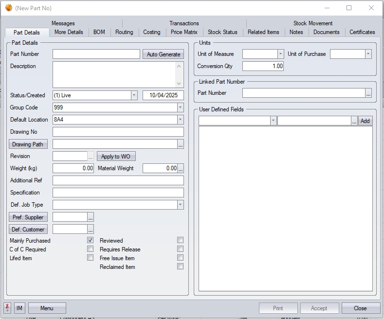
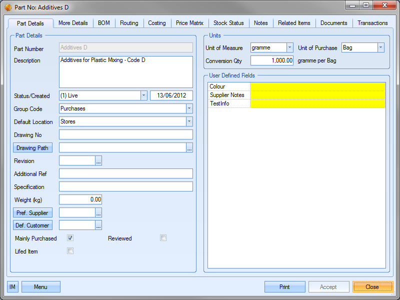
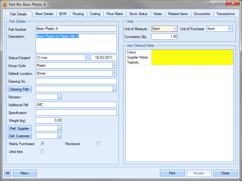
Part Details
This section of the inventory record contains the main information about a part.
| Part Number | This is the unique identifier of the part. Every part that is manufactured or bought requires a part number. The user can enter a specific part number, choose for the system to auto generate a part number using the AUTO GENERATE option or use a combination of them both. |
![]()
Example 1 – Manual part number
Once the user clicks the ACCEPT option, and assuming the part number has not already been used, the part is created with the exact part number entered by the user.
![]()
Example 2 – Auto generated part number
Once the user clicks ACCEPT option to record the part details, Progress will allocate the next available numerical number as set in the system numbers as the part number. In this example, 2.
![]()
Subsequent auto generated numbers will continue this sequence.
![]()
Example 3 – Combination of both options above
The user can enter any prefix text they wish to use as well as click the AUTO GENERATE option. Once the user clicks the ACCEPT option to record the part details, Progress will add the next available four-digit number to the end of the part number entered.
![]()
| Description | This is the full text description of the part up to a maximum of 255 characters. |
| Status/Created | This is the status of the part. This field will default to whatever status has been assigned as the default in the Maintenance > Inventory Status list. The user can change the status of the part by selecting from the drop-down list. |
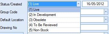
This drop-down list can be populated from the Maintenance section of Progress in the Inventory Status list as shown in the screen below.
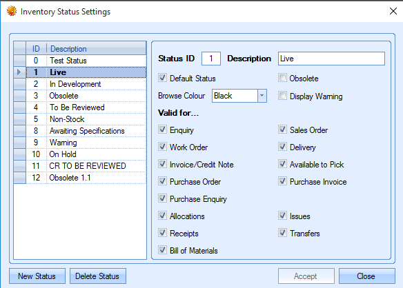
More information on this screen can be found in the Maintenance > Inventory Status section of this manual.
The date field shown next to the part status field is the date the part was created. This defaults to the current date and cannot be changed.
| Group Code | This field allows the user to specify a group code for the part. All parts MUST have a group code specified. The user can select the required group code from the drop-down list. |
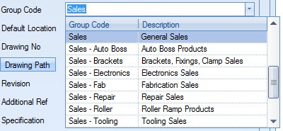
This drop-down list can be populated from the List Maintenance section of Progress in the Group Codes list as shown in the screen below.
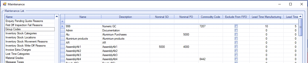
For more information on maintaining lists and the List Maintenance section of Progress, please refer to the List Maintenance section of this manual.
| Default Location | This field allows the user to set the default stock location to be used for this part. The user can select a stock location from the drop-down list. |
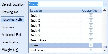
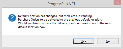
This will be the default location whenever the part number is being receipted on a purchase order or on a work order. If the user changes the default location against a part, the system will prompt the user to update the location recorded against any outstanding purchase order lines for the selected part (the default location is recorded against PO lines when initially created).
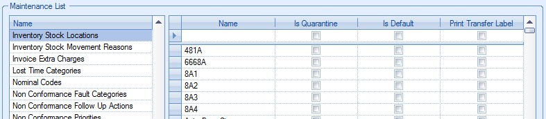
The drop-down list of locations is populated from the List Maintenance section of Progress in the Inventory Stock Locations list as shown in the screen below.
For more information on maintaining lists and the List Maintenance section of Progress, please refer to the List Maintenance section of this manual.
| Drawing Number | This field allows the user to record a drawing number for the part if applicable. |
![]()
| Drawing Path | This field allows the user to link the part directly to the drawing document or file specified above. This can even be an online web address. |
![]()
The user can select the required document by clicking on the ![]() option at the end of the field. This will present the user with the following screen which they can use to locate and select the file.
option at the end of the field. This will present the user with the following screen which they can use to locate and select the file.
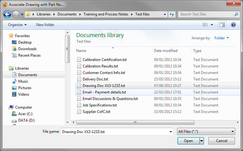
Once the file has been selected, the file path is recorded in the field.
![]()
| If the user wishes to record a web address, they can simply paste the URL into the DRAWING PATH field. |
The DRAWING PATH button at the start of this field allows the user to open the specified file/URL directly from the part record, assuming they have an application suitable for viewing the specified file type.
| Revision | This field allows the user to specify the part revision. |
![]()
When a part is initially being set up, the user can specify a revision number or character if this is required.
Once a part has been created, the user has the ability to increase the part’s revision, as well as record the date of the change and who done it. Users can add additional revisions and see the revision history by clicking on the ![]() option at the end of the field. This presents the user with the following screen.
option at the end of the field. This presents the user with the following screen.
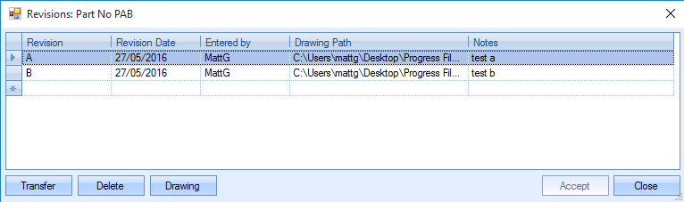
The user can add additional revisions by completing the blank line available at the bottom of any listed revisions. The Revision Date and Entered By information will default to the current date and user ID. The drawing path can be selected for that specific revision by using the ![]() button in the Drawing Path column. Once the details have been entered, the user can save the changes by clicking on the ACCEPT option.
button in the Drawing Path column. Once the details have been entered, the user can save the changes by clicking on the ACCEPT option.
To select a revision the user must highlight the required revision and click on the TRANSFER option to return the selected revision to the part record. This will update the revision to the selected revision and change the drawing path accordingly.
![]()
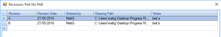
The user can also delete a revision by highlighting the line and selecting the Delete button.
The Drawing button will open the drawing of the revision highlighted, providing there is a suitable drawing path for that revision.
| Additional Ref | This field allows the user to add an alternative reference for the part being created. |
![]()
| Specification | This field allows the user to enter specification details for the part being created. |
![]()
| Weight (kg) | This field allows the user to record a weight against the part. This is used typically for INTRASTAT purposes and commercial invoices, but can be included on delivery documents if required. If the part is an assembly and has subcontract operations on its routing that are priced based on weight, the system will default the part's weight onto the subcontract operations. If the user updates the part weight value, and the part has subcontract operations on its routing that are priced by weight, the system will prompt the user to ask whether they want the subcontract operation weight values to be updated. |
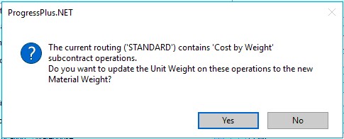
Clicking YES will update the weight values on all relevant subcontract operations.
| Material Weight | This field allows the user to record the total material weight of the part. This can be manually entered or, if an assembly part, be calculated based on its BOM components' weights. |
![]()
This can be done by clicking on the three dots against the field which will present the user with the following screen.
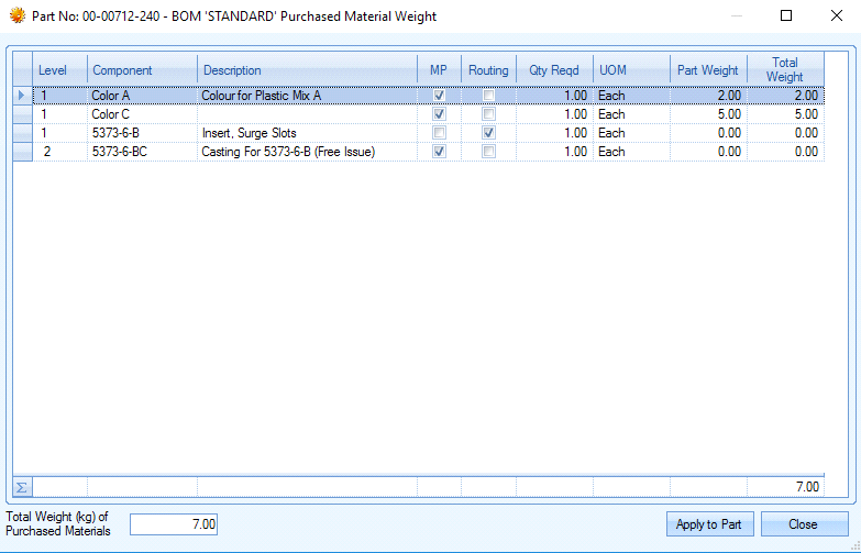
| This screen will allow the user to view the component parts on the BOM of the top level part. If there is a weight in the Part Weight field, the system will add these weights together and total them in the bottom left and right of the screen. |
| The use can simply click the APPLY TO PART button and the system will roll up the individual part weight's and shows these as a total weight figure against the top-level part. |
![]()
| This will now display the MATERIAL WEIGHT of the BOM items on the part record as shown below. |
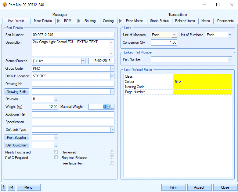
(Updated Top-Level Part)
| If the part has subcontract operations on its routing that are priced by weight, changes to this field will ask the user whether they wish to update the subcontract operations with the new value. |
Clicking YES will update the subcontract operation weights.
| By default, any subcontract operations on the part's routing which are costed based on weight will default the weight value to the PART WEIGHT value, however, if the user would prefer to use the Material Weight value, this can be configured in the system settings. |
![]()
| For more information on this option, please refer to the system options section of this manual. |
| Pref. Supplier | This field allows the user to choose a preferred supplier for this item from a list of previously entered suppliers. This field is used for entering a supplier against mainly purchased items. Supplier information will default to the preferred supplier specified when the part appears on the PO shortage screen. |
![]()
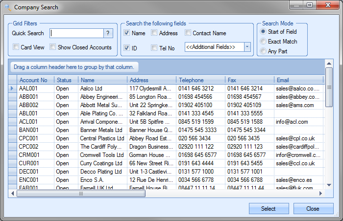
The user can select a preferred supplier by clicking on the ![]() button at the end of the field. This will present the user with the supplier list to choose from. If the APPROVED SUPPLIER filter is in use, the screen will present a list of approved suppliers for the user to select from.
button at the end of the field. This will present the user with the supplier list to choose from. If the APPROVED SUPPLIER filter is in use, the screen will present a list of approved suppliers for the user to select from.
![]()
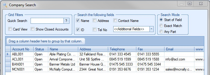
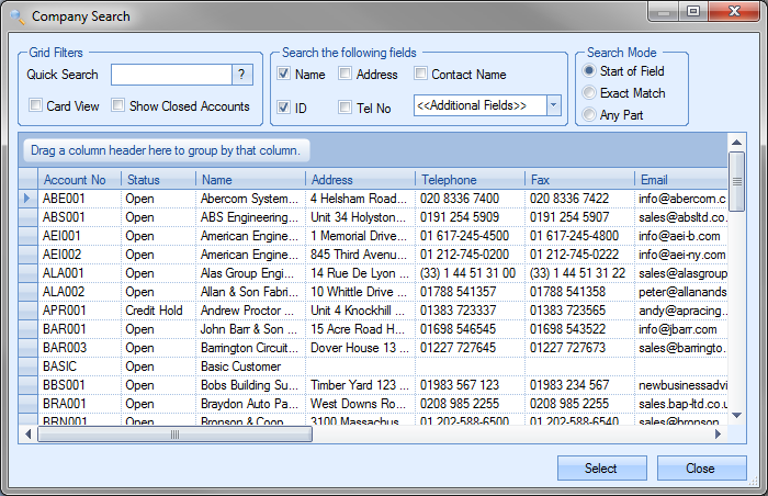
If the APPROVED SUPPLIER option is not in use, the user will be presented with every supplier currently available in Progress.
![]()
For more information on approved suppliers option, please refer to the Administrator Functions section of this manual.
The user can select the required supplier from the list and click the SELECT option to return to the part record.
![]()
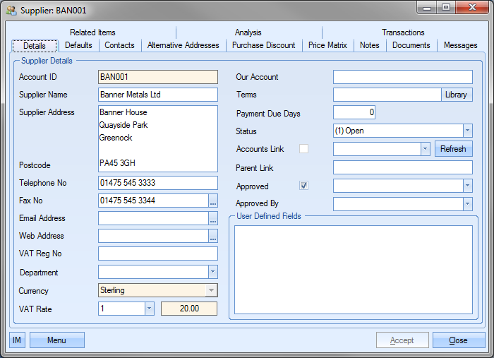
Once a supplier has been selected for a part, the user can view the supplier details directly from the part record by clicking on the PREF SUPPLIER button. This will open the supplier record for the user to view.

The user can view or amend the supplier details if their access allows.
| Def. Customer | This field allows the user to choose a default customer for this item from a list of previously entered customers. Specifying a default customer allows the user to filter some inventory reports to view customer specific parts and can be used for both mainly purchased and manufactured parts. |
![]()
The user can select a customer by clicking on the ![]() button at the end of the field. This will present the user with the customer list to choose from.
button at the end of the field. This will present the user with the customer list to choose from.
The user can select the customer from the list and click the SELECT option to return to the part record.
![]()
Once a customer has been selected for a part, the user can view the customer details directly from the part record by clicking on the DEF CUSTOMER button. This will open the customer record for the user to view.
The user can view or amend the customer details if their access allows.
| Mainly Purchased | This option allows the user to specify whether the part is a purchased part from a supplier or a manufactured item. |
![]()
Sometimes a part will be mainly purchased but if the user has more time he may choose to manufacture the item in-house. If this item is in turn used on the BOM for other parts the system requires to know if the part is Mainly Purchased so it can suggest raising a purchase order for any shortfall or if it is not mainly purchased it will suggest that the user should raise a works order to satisfy requirements. The user may choose however to ignore a purchase order suggested by the system and choose to manufacture the part if desired. If this box is not ticked the system will assume that it is a manufactured item and treat it accordingly.
| Reviewed | This option allows the user to specify whether the part has been reviewed. This is used as a visual indicator only. |
![]()
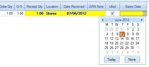
| Lifed | This option allows the user to specify whether the part has a shelf life or expiration date. |
![]()
If the option is ticked receipt of the item, whether it’s via a purchase order or a work order, will expect the user to specify an expiration date as part of the receipt information. This information is recorded against the GRN record.
Inventory with expiration dates can be monitored via the Today > To Do screen using the Parts Due To Expire section. This highlights any inventory where the expiration date falls within the specified number of days. For more information on the To Do screen, please refer to the Today section of this manual. If lifed items are not used within the business, the inventory option can be removed completely by ensuring the following inventory admin option is unticked.
![]()
For more information on the inventory admin options, please refer to the Miscellaneous & Inventory system options section of the manual.
CofC Required This option indicates that the part requires a CofC from a supplier (if purchased), or a CofC should be provided to the customer (if sold).
![]()
| If this option is ticked, the CofC Required option will be ticked on purchase order lines and/or sales order lines when the part is added to either. |
| From a purchasing perspective, this can be used to indicate to a supplier that a CofC is to be provided upon delivery and also to highlight to those receiving the goods that one should be present. |
| From a sales perspective, this can be used to highlight to both sales and despatch departments that a CofC is to be sent with the goods. |
| Requires Release | This option determines whether batches/GRNs of this part are placed on automatic hold when receipted into stock and applies to all receipt types. |
![]()
| Having this option ticked will automatically tick the REQUIRES RELEASE option on all receipt screens for this part. Leaving this unticked will default the REQUIRES RELEASE option on all receipt screens as unticked, however, the user will be able to tick it if that specific batch is to be placed on hold. |
Any batches received into stock and placed on hold will show against the part's ACTIVE stock figure however the "requires release" quantity will show in brackets next to the total. Each batch will also be highlighted as being "requires release" too on the grid to the right.
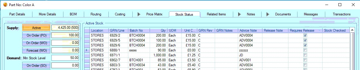
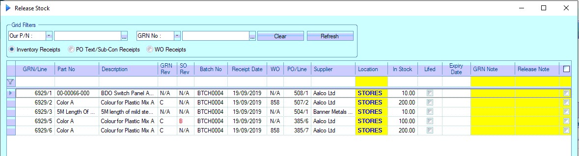
Any batch that is "on hold" can be released into available stock using the Requires Release screen which can be found in the Inventory section of Progress. Please refer to the section of the manual for this screen for further information.
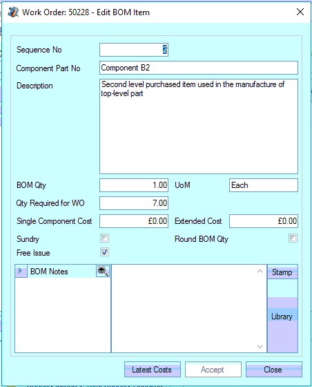
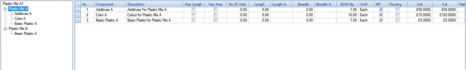
| Free Issue Item | This option allows the part to be marked as a FI (free issue) part. This is used to indicate that a part will be supplied by another party, typically the customer. |
![]()
| This allows the part to be included in BOMs but not generate demand for the purchasing or production departments to action (i.e. no POs or WOs required). It will also remove any associated costs from job costing calculations in the system (i.e. because its not a cost you will incur). For assembly items, this flag will do the same but will result in all costing calculations associated with the part to ignore any labour, subcon or material costs that are set up on its BOM or ROUTING. |
| This FI flag is shown alongside the part throughout the system for the user's reference, appearing on all relevant screens. These include the BOMS, SO Line Requirements, WO Demand, PO Shortage and Below MSL screens with most having an option for FI items to be filtered out. |
| If the part is added to a BOM for an assembly item, the flag will default against the BOM item based on the master part record. This can be edited on the work orders BOM details if it needs to be different to the default FI setting on the part number. |
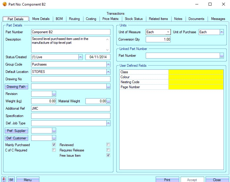
(Component FI part)
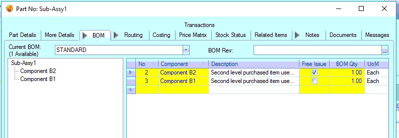
(Assembly BOM with Component FI Part)
| Similarly, when a WO is raised for an assembly part, the WO BOM items will pull through based on the assembly part's BOM. Any component or sub-assy part on the top-level assemblies BOM will be marked accordingly on the WO BOM. |
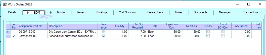
(WO BOM for Assembly with FI Component)
| Again this can be changed at the WO level if different from the assembly's default configuration for the specific job. This can be done in the WO BOM item's details. |
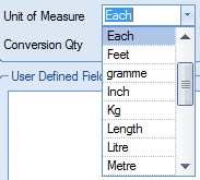
| Unit of Measure | This field allows the user to specify the measurement by which the parts is recorded and used within Progress. The Unit of Measure (UoM) is used when referring to all part quantities within Progress EXCEPT on purchase orders. |
![]()
The user can specify the measurement used for UoM by selecting from the drop-down list.

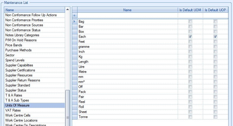
This drop-down list is populated from the List Maintenance section of Progress in the Units of Measure list as shown in the screen below.

For more information on maintaining lists, please refer to the List Maintenance section of this manual.
| Unit of Purchase | This field allows the user to specify the measurement by which the part is purchased from the supplier. The Unit of Purchase (UoP) is used when referring to part order quantities on purchase orders. |
![]()
The user can specify the measurement used for UoP by selecting from the drop-down list.
All items, whether they are purchased or manufactured in-house, will have a UoP. If the user does not enter a UoP, the system will default to “Each”. The drop-down list is populated from the List Maintenance section of Progress in the Units of Measure list as shown in the screen below.
| Conversion Qty | This is the quantity used to convert between the Unit of Purchase (UoP) and the Unit of Measure (UoM) upon purchase order receipt. |
![]()
For example, screws are bought in boxes of 500, but they are used individually in the manufacturing process. Our PO would specify the number of boxes we want to buy but, upon purchase order receipt, we want to see the quantity in stock as the number of screws, so our Conversion Qty would be set to 500. Therefore, for every box received from the supplier on a purchase order, we would see 500 screws in inventory.
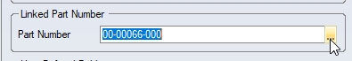
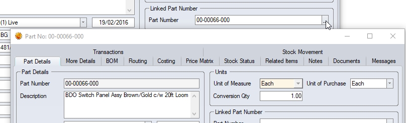
| Linked Part Number | This field allows the user to link the part number to another part number. This can be useful if the new part is a replacement part for an existing one, and provides quick access to its previous incantation for historical reference. |
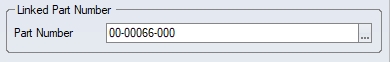
| If a part is linked, clicking the box at the end will open the linked part number for the user to see. |
| User Defined Fields | If any user defined fields have been configured for the parts records, they will be listed in the section shown below. |
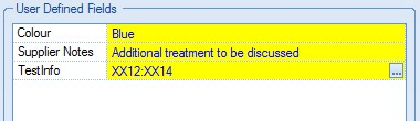
For more information on user defined fields, please refer to the Maintenance section of the manual.
More Details
This section of the inventory record contains the additional information about a part.
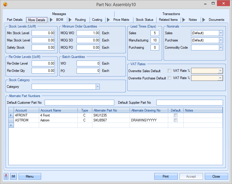
| Min Stock Level | This is the minimum stock level that the user wishes to hold of this item at any time. |
![]()
Should the projected quantity of this item held in stock fall below this level this item will appear on the Stock Shortages Report within the Reports section of Progress and on the Stock Status screen as a shortage. The values entered into this field should relate to the UOM.
| Max Stock Level | This in the maximum stock level that the user wishes to hold of this item at any time. |
![]()
| This is used as a reference for the part but will not affect any purchases or shortages for that part. |
| Safety Stock | This is the stock level that the user wishes to hold to maintain normal production requirements – usually a figure higher than that of the Minimum Stock Level. |
![]()
It is not used within the system for any calculations but is there as a visual aid. The values entered into this field should relate to the UOM.
| Re-Order Level | This is the level held of this item at which the user wishes to re-order this item to maintain a sufficient stock level e.g. re-order level equates when stock of this part reaches this level the user wishes to replenish his stock of this item either by raising a purchase order or a works order for this item. The values entered into this field should relate to the UOM. |
![]()
| Re-Order Qty | This is the batch quantity that the user prefers to purchase this item in. The values entered into this field should relate to the UoP. |
![]()
| MOQ WO | This field allows the user to specify the minimum quantity to manufacture on a work order. This may be due to minimum customer order quantities or due to the cost ineffectiveness of manufacturing smaller quantities. The quantity entered relates to the UoM. |
![]()
| MOQ SO | This field allows the user to specify the minimum quantity to sell on a sales order. This may be due to minimum quantities that can be supplied to the customer or because it’s not cost effective to sell quantities less than this value. The value entered relates to the UoM. |
![]()
| MOQ PO | This field allows the user to specify the minimum quantity to be ordered on a purchase order. This may be due to minimum quantities that can be supplied by the supplier or because it’s not cost effective to buy in smaller quantities. The value entered relates to the UoP. |
![]()
| Batch Quantity WO | This field allows the user to set batch quantity for creating Work Orders. This will affect the suggested quantity when using the Below MSL screen and Sales Order Line Requirement screen. The value entered relates to the UoM. |
| Batch Quantity PO | This field allows the user to set batch quantity for creating Purchase Orders. This will affect the suggested quantity when using the PO shortage screen. The value entered relates to the UoP. |
| Sales Lead Time | This is the number of days lead time to be taken into consideration when a sales order is raised for this part. The SO line requirement date will default to the current date plus any sales lead time specified against the part. |
![]()
| Manuf. Lead Time | This is the number of days lead time taken to manufacture the part. This value is used to calculate the work order start date from the sales order requirement date. This value is used in conjunction with any margins of error that have been set up for work order start and finish dates. |
![]()
For more information on manufacturing lead times and margins of error in relation to work order dates, please refer to the System options for work orders.
| Purch. Lead Time | This is the number of days lead time taken to purchase the part. This value is used to calculate the date by which the purchased material needs to be ordered to ensure it’s received by the work order start date. |
![]()
| Sales Nominal | This field allows the user to select a specific accounts nominal for the part. |
![]()
The user can select the nominal from the drop-down list.
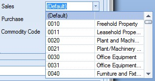
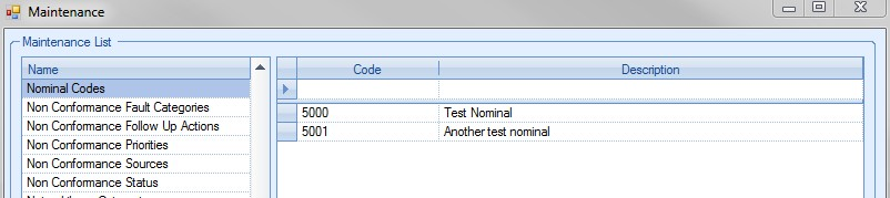
If Progress is linked to an external finance package, the nominal list will show all available nominals set up in the accounts package. If Progress is not linked to an external accounts package, the drop-down list will show all nominals set up in the List Maintenance section of under the Nominal Codes section.

Selecting a specific nominal against the part will override any nominal associated with the Group Code of the part. When left as (DEFAULT) the nominal will default to the nominal set up against the chosen Group Code. If no sales nominal has been set up against the Group Code, then the nominal will default to that of the customer the part is being sold to. If no nominal has been set up against the customer then the nominal will default to the default sales nominals set up in the System Accounts Link options.
| Purchase Nominal | This field allows the user to select a specific accounts nominal for the part. |
![]()
The user can select the nominal from the drop-down list.
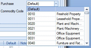
If Progress is linked to an external finance package, the nominal list will show all available nominals set up in the accounts package. If Progress is not linked to an external accounts package, the drop-down list will show all nominals set up in the List Maintenance section of under the Nominal Codes section.
Selecting a specific nominal against the part will override any nominals associated with the Group Code of the part. When left as (DEFAULT) the nominal will default to the nominal set up against the chosen Group Code. If no purchasing nominal has been set up against the Group Code, then the nominal will default to that of the supplier the part is being bought from. If no nominal has been set up against the supplier then the nominal will default to the default purchasing nominals set up in the System Accounts Link options.
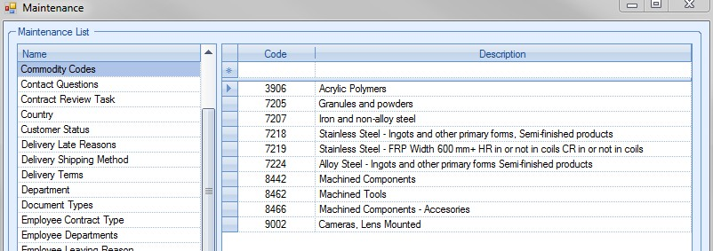
| Commodity Code | This field allows the user to specify a commodity code group for the part. |
![]()
The user can select a commodity code from the drop-down list. The drop-down list is populated from the List Maintenance section of Progress in the Commodity Codes list as shown in the screen below.
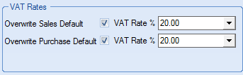
| VAT Rates | These options allow the user to set an overriding VAT rate for sales orders and purchase orders when the part is added to the respective order. This value will override the customer or supplier's VAT rate. |
| Default Cust Part No | This field allows the user to specify a default customer part number. This can be used where the Progress part number is not the same as the customer part number or where the customer specifically wants to see their part number on documents generated by Progress. |
![]()
| Default Supp Part No | This field allows the user to specify a default supplier part number. This can be used where the Progress part number is not the same as the supplier part number or where the supplier specifically wants to see their part number on documents generated by Progress. |
![]()
In the event that the part being created has multiple different aliases depending on the customer or supplier being used, the user can set up multiple references to the part specific to the suppliers and customers in question. This can be done using the grid below.
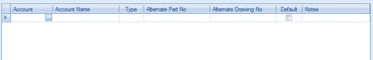
The user can select a supplier or customer by clicking on the ![]() option at the right of the Account column. This will present the user with a list of all customers and suppliers to choose from.
option at the right of the Account column. This will present the user with a list of all customers and suppliers to choose from.
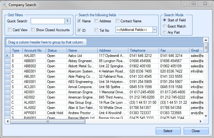
The user can select the supplier or customer required and press SELECT to return to the part screen. This can be repeated for as many different references as required for the part.
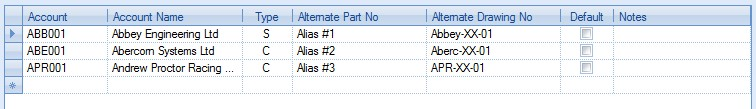
These aliases can then be used to reference the correct supplier or customer part number for any documentation.
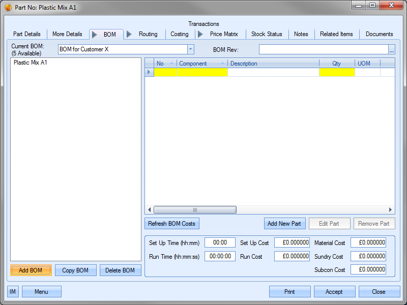
BOM
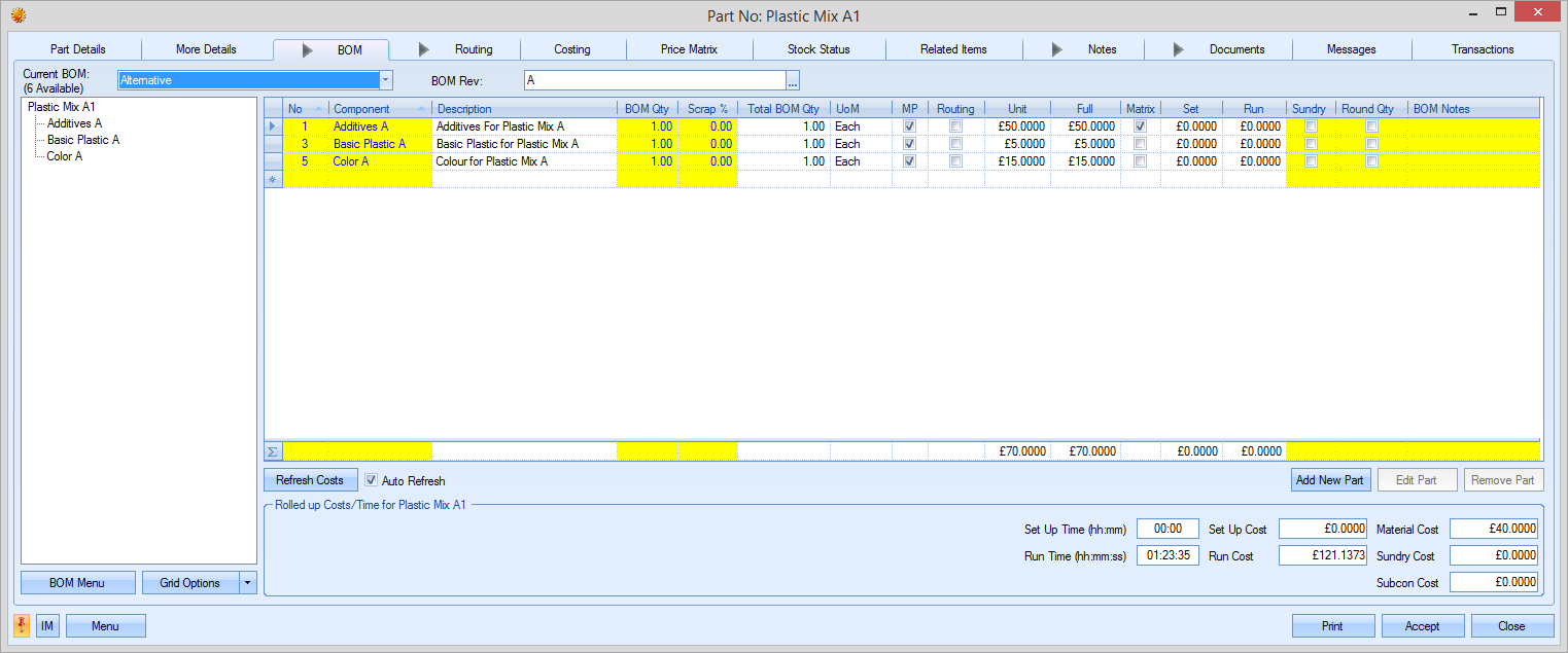
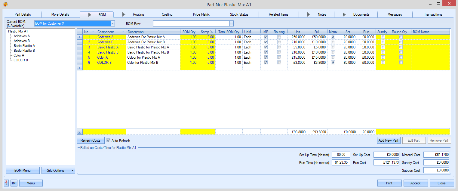
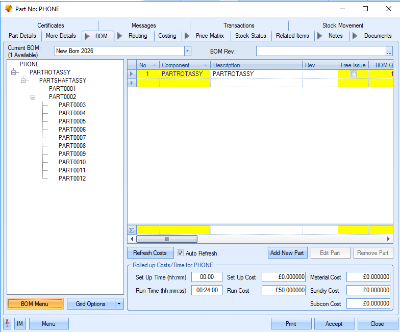
This screen allows the user to list any purchased or sub-assembly items used in the manufacture of the current part.
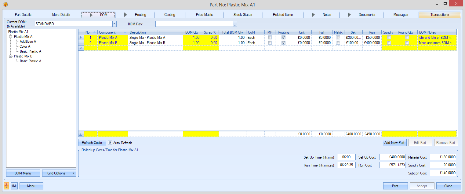
For purchased parts, this screen will be left empty as there will be no component parts for a purchased item. For a manufactured part, this screen allows the user to specify one or more component lists that can be used for the manufacture of the item. An example manufactured part is shown in the screen shot above.
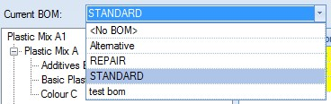
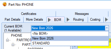
The drop-down list at the top of the screen allows the user to select the BOM to be used for the part. By default, the first BOM is labeled “STANDARD”. Subsequent BOMs can be labeled however the user desires.
BOM Revisions
The user can record revision history against each BOM in the system using the BOM Revision field at the top of the screen.
![]()
The user can record revisions against the BOM by clicking on the ![]() option at the end of the field. This will present the user with the following screen.
option at the end of the field. This will present the user with the following screen.
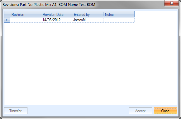
The user can record the revision ID and any notes associated with the revision. The date will default to the current date and the user to the current Progress user. Once the details have been added, the user can select the revision by highlighting the required revision and clicking on the TRANSFER option. This will return the user to the BOM screen and attach the selected revision.
Once the user has added a revision to the BOM, they can save the changes by clicking the ACCEPT option. Additional revisions can be added and selected as and when required.
Changing BOMs
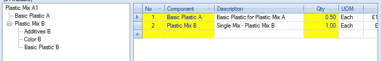
Selecting an alternative BOM will result in the details on the screen being updated accordingly as shown below.
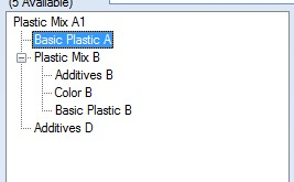
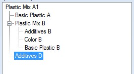
The current selected BOM is shown as a “tree view” in the box to the left of the screen. This shows the different BOM levels contained within the BOM.
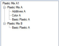
Selecting different parts within the “tree view” results in the component details being shown in the box to the right. By default, the details of the first level of the BOM are shown.
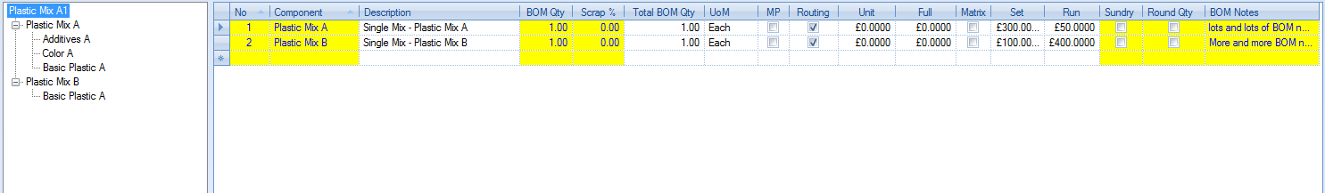
Selecting one of the sub assembly components lists the component parts for that part in the right hand section of the screen.
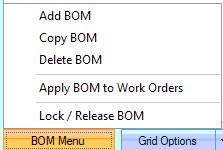
BOM MENU
Manufactured part’s BOMs can be created, copied, amended or deleted from this screen using the various options. The options in the BOM Menu option at the bottom left of the screen allow the user to create new BOMs, copy existing BOMs from other manufactured parts or delete existing BOMs. The user can also lock BOMs so they cannot be edited.
Add BOM
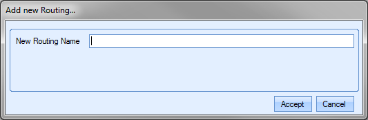
The user can create additional BOMs for the selected part by clicking on the ADD BOM option. When selected, the user is asked to provide a name for the new BOM.
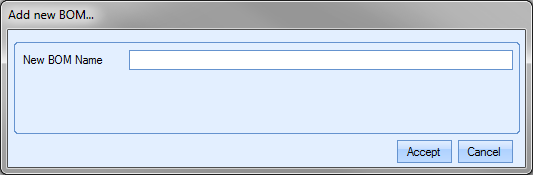
The name provided can be anything, but it’s often used to indicate the purpose of the additional BOM; a customer reference or reference to a particular component part or material that is used. Once entered the BOM screen is updated with the new BOM which, by default, will be blank. The user can then add the purchased and/or sub-assembly parts required for the BOM. The new BOM name can also be seen in the CURRENT BOM drop-down list at the top of the BOM screen too.
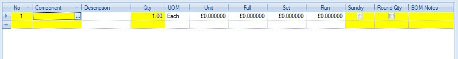
To add new components to the BOM, the user can either click on the highlighted yellow “component” box in the grid to select existing Progress part numbers or click on the ADD NEW PART option immediately under the grid to add new parts not currently available on Progress. For more information on adding component parts to a BOM, please refer to the BOM Component Maintenance section of this manual.
Copy BOM
This option allows the user to copy an existing BOM from another part in Progress. This is particularly useful when large-scale BOMs are used and there are similarities between manufactured items. When the user selects the COPY BOM option, the following screen is displayed.
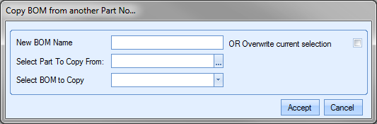
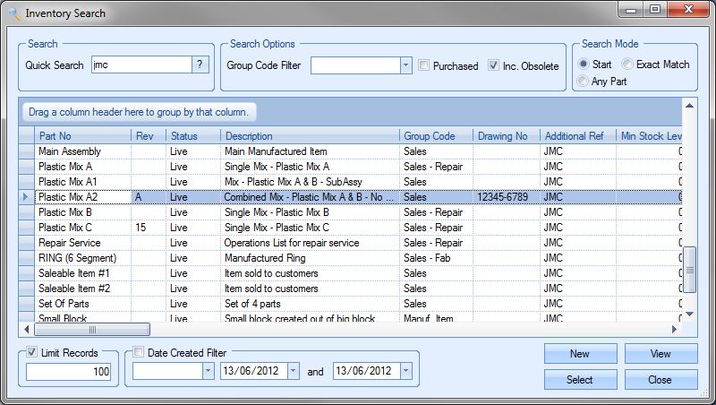
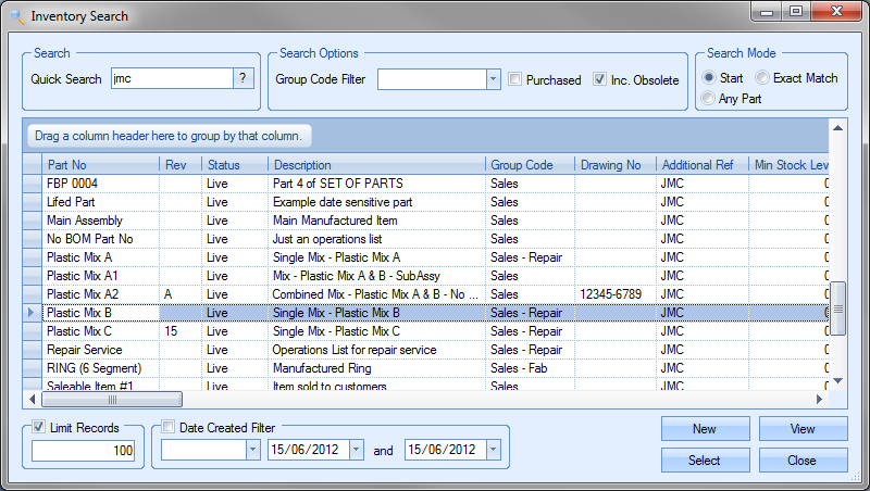
The user can choose to create a new BOM by entering a name for the new BOM or overwrite the currently selected BOM by ticking the overwrite option. The user must then select the part number that has the required BOM. They can do this by clicking on the ![]() option at the end of the field. This will present the user with the Inventory Search window. The user can then search for the part number required.
option at the end of the field. This will present the user with the Inventory Search window. The user can then search for the part number required.

Once the user has identified the part required, clicking the SELECT option will return the part to the COPY BOM screen.
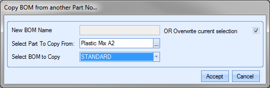
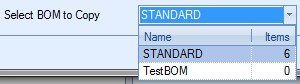
Finally, the user can select the BOM using the drop-down list.
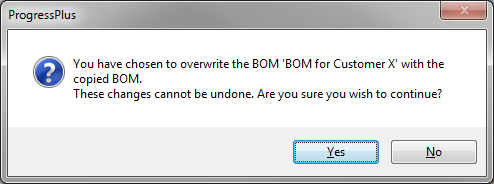
Once selected, clicking the ACCEPT option prompt the user to confirm the change before pulling the BOM details through to the BOM screen.
The user can now make additional changes to the BOM quantities or components as necessary. Once finalised, the user must click the ACCEPT option to save the new BOM details. The new BOM is now ready for use.
Delete BOM
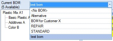
This option allows the user to delete existing BOMs from the manufactured part. This option could be used if older BOMs have become obsolete and the user chooses to remove them from the part. To delete a BOM, the user must firstly select the BOM from the drop-down menu at the top.
Once the BOM to be deleted has been selected, the user can click the DELETE BOM option. The user will be prompted to confirm the deletion.

Once the user confirms, the BOM information will be cleared from the screen and the part will default to the <NO BOM> option.
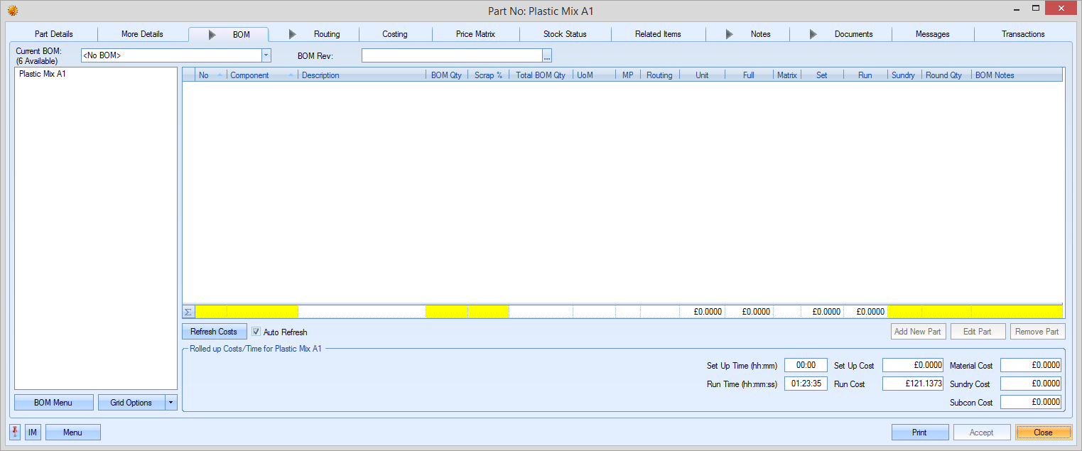
The user can now select the BOM the wish to use going forward from the drop-down list at the top of the screen or create a new BOM if required. Again, clicking the ACCEPT option will save the changes made.
Apply BOM to Work Orders
This option allows the user to push amendments to BOMs to existing WOs. The user will be prompted to select the WOs to be updated as shown below.
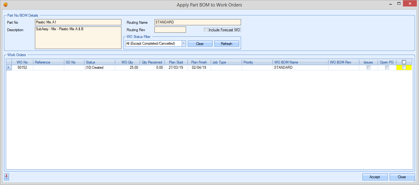
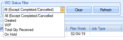
The user can use the status filter to narrow down the list of WOs that are to be updated. By default, the system will suggest all WOs (except cancelled or complete WOs), although this can be changed. Clicking REFRESH will update the list of WOs shown.
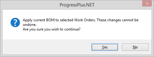
Once the user has selected the WOs to be updated, clicking ACCEPT will prompt the user to confirm the update before updating the selected WOs.
Lock/Release BOM
This option allows permitted users to lock a BOM so it cannot be edited. This is a user permission and is set against the user's access permissions in the Admin section of progress. This option will only be available to users who have this permission. When a BOM is locked, a small padlock icon will be displayed against the BOM tab to indicate such. The BOM can be viewed but cannot be edited until its unlocked by an authorised user.
![]()
Structured BOM import
NOTE: This option must be switched on by Progress Plus. Please contact them for more details/activation.
This option allows the importing of a structured BOM from a spreadsheet and was created based on the output of the SolidWorks CAD software. The import process requires 4 mandatory pieces of information, which are as follows:
•Level (i.e. the BOM structure)
•Child part no
•Child part description
•BOM quantity (i.e. how many is required for the assembly)

The user can add additional fields to the import as long as the additional fields match the standard BOM import template field names. For more information on the standard BOM import process, please refer to the Tools > Import/Export Data section of the manual.
The first step before carrying out the import is to create the master part (i.e. the assembly part). This can be done in the Inventory > Part List section of Progress Plus, clicking the NEW option and completing the part details. For more information on creating parts in Progress Plus, please refer to the Inventory > Part List section of the manual.
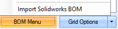
Once the main assembly part number has been created, the user can then import the BOM. This is done using the MENU > IMPORT SOLIDWORKS BOM option.
Selecting this option will present the user with the BOM import screen.
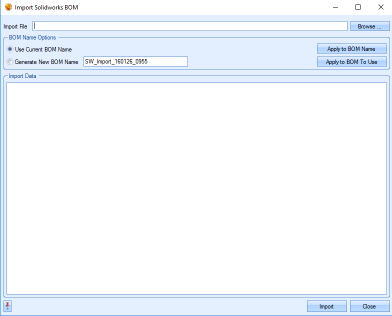
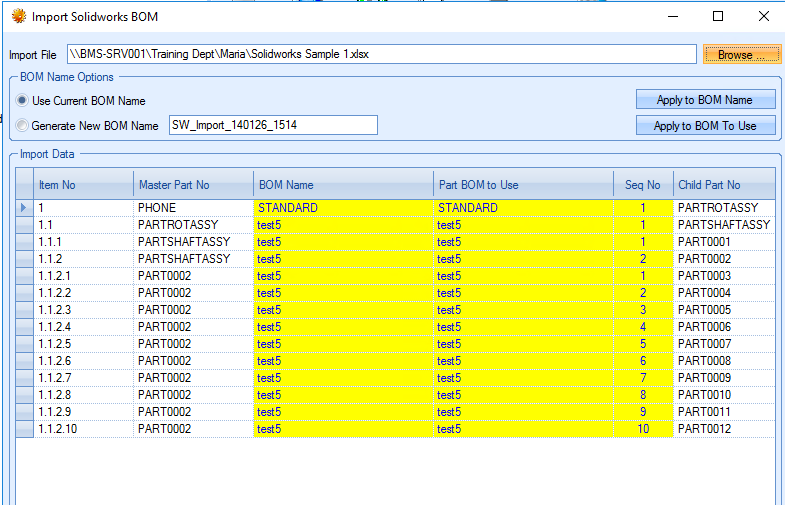
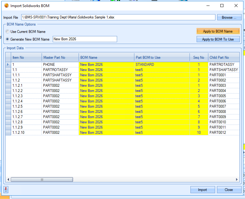
The user must firstly select their import file. This is done by clicking the BROWSE option and selecting the file to import. Once selected, the user should see the imported BOM details in the grid below.
The user can now select whether they wish to overwrite the currently selected BOM or create a new BOM name from the import.
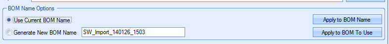
When the import spreadsheet is loaded, the BOM name in the grid will be set to reflect the part’s current BOM name by default. For new assembly parts, this will be the default name of “STANDARD”, with all lower level BOMs named with a generic name based on the current date/time.
If the user chooses to create a new BOM name, they can specify this, and also apply the name to the import using the APPLY TO BOM NAME and APPLY TO BOM TO USE options. The APPLY TO BOM NAME option updates the import details with the BOM name the user has specified. Importing the BOM at this stage will create a new BOM for the assembly with the specified name but will NOT set the new BOM as the default BOM for the assembly part.
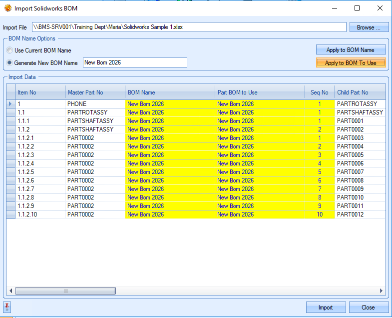
The APPLY TO BOM TO USE option updates the import details to set the new BOM as the default BOM for the assembly part. Importing the BOM at this stage will create a new BOM for the assembly with the specified name AND will set the new BOM as the default BOM for the assembly part.
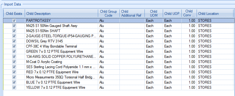
The user can review and amend any details at this stage if they wish. The BOM displayed includes all additional inventory fields for importing, allowing the user to amend and/or add information prior to importing. The user can scroll the BOM to the right to see all the available fields. If the BOM part number already exists in Progress, the existing details for the part will be displayed.
Once the user is happy with the BOM details, they can import the BOM using the IMPORT option at the bottom of the screen. Once complete the user will get a confirmation message to let the user know it was successful.
If there are any issues with the import, the system will generate a text file listing the issues that need to be addressed.
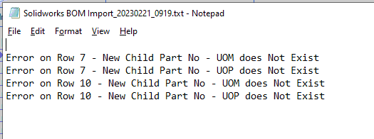
Once the issues have been corrected, the user must repeat the import process above.
When the import is complete, the BOM will be available against the part.
If the user applied the APPLY TO BOM TO USE option, the new BOM will be shown as the current BOM. If the user chose to only import the BOM (i.e. didn’t use the APPLY TO BOM TO USE option), then the new BOM will be available from the drop-down menu at the top of the BOM tab.
NOTES:
•The master part (i.e. the assembly) should not be included in your import spreadsheet. This will be automatically added to the import details when the user selects the import file.
•Any child part(s) that already exists in progress have the CHILD EXISTS field ticked and will show its existing information from Progress Plus.
•Any new parts included on the import sheet which do not already exist in Progress Plus will be created as part of the import process. The user will be prompted to add any default information that is missing when the user tries to import. For example, default location, UOM, UOP, etc. If default values have been set for any of these in the system (i.e. in the Maintenance > List Maintenance section), these will be used for all new parts.
BOM Component Management
BOM parts, both manufactured and purchased, can be added, amended or deleted from this screen using the various options available. Existing Progress parts can be selected directly via the BOM grid or the user can use the following options.
![]()
Adding Existing Progress Parts to a BOM
If the user wishes to add an existing Progress part to a BOM, they can add it via the BOM grid.
Clicking on the yellow Component field presents the user with the ![]() option that will allow them to search for the part number required.
option that will allow them to search for the part number required.
Clicking on the ![]() option opens up the Inventory Search window from which the user can search.
option opens up the Inventory Search window from which the user can search.
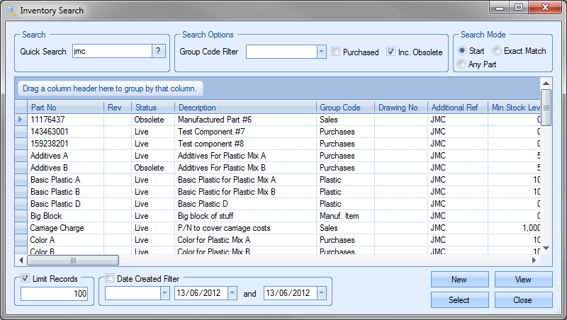
Once the required part has been identified, clicking the SELECT option will return the part to the BOM grid.

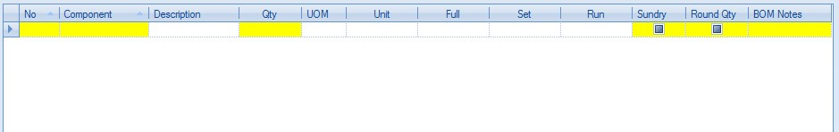
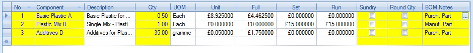
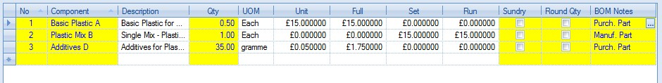
The information in the grid is as follows:
| No | This is the BOM sequence number. This is a sequential number generated by Progress, although this can be amended by the user if required. |
| Component | This is the Progress part number selected for the BOM. |
| Description | This is the description recorded against the selected part in the inventory record. |
| Qty | This is the BOM quantity and is the qty of the component required to manufacture one unit of the manufactured item. |
| UoM | This is the unit of measure (UoM) of the component part. |
| Unit | This is the unit cost of one unit of the selected part. For manufactured parts, i.e. sub-assemblies, this will always be zero. For purchased parts, this will either be the STANDARD COST or the LAST PRICE of the part depending on how the costing options have been configured in the system options. |
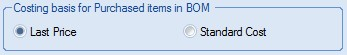
For more information on these options, please refer to the Costing Defaults section in the Admin section of the manual.
If the system is configured to use the LAST PRICE option, the system will display either the part's purchasing cost or a price matrix price if one is set. If a suitable price matrix is set up for the part in question, then the relevant price matrix price will be displayed and highlighted using the PRICE MATRIX flag against the BOM item.
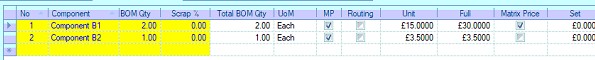
| Full | This is the full cost of the purchased part based on the UNIT cost and the BOM quantity entered. |
| Set | This is the set up cost associated with the part. For purchased parts, this will always be zero. This is only associated with manufactured parts on the BOM i.e. sub-assembly items. This is calculated based on the cost per hour of the sub-assembly work centres and the set up times associated with them. |
| Run | This is the run cost associated with the part. For purchased parts, this will always be zero. This is only associated with manufactured parts on the BOM i.e. sub-assembly items. This is calculated based on the cost per hour of the sub-assembly work centres and the run times associated with them. |
| Sundry | This option allows the user to specify whether this part has a one-off cost associated with the BOM or whether the cost increases based on the manufactured quantity. |
| Round Qty | This option allows the user to specify whether the BOM quantity is rounded up to the nearest full unit of purchase (UoP) quantity when calculating part shortages and costs. Full cost of BOM item will reflect this even though the BOM quantity may only be a fraction of what is being purchased. This ensure the system includes the cost of a full bar, sheet, etc. if not able to purchase an exact quantity required. |
| Subsequent WOs created will also increase the BOM requirement to the full UOP quantity to ensure enough material is ordered. |
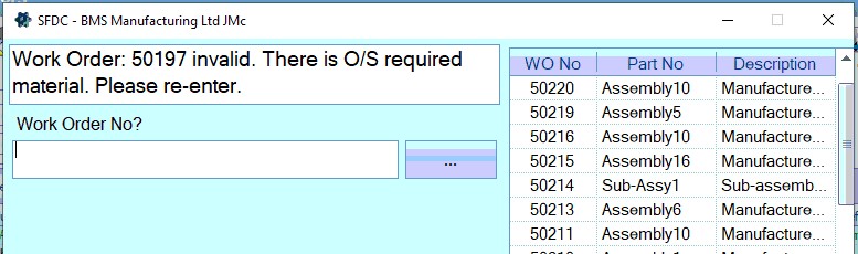
| Req'd To Start | This option allows the user to indicate that the component part is required for the WO to start. This option needs to be switched on in the Inventory > BOM system options. Please refer to the relevant section of the Administrator Functions section of the manual. When this option is ticked, the system will not allow an employee to job on to/create a timesheet against any WOs for an assembly where the component part has not been fully issued to the WO. Attempting to job onto a WO or create a manual timesheet will result in the following messages being displayed. |
(Jobbing on via SFDC)
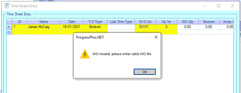
(Creating manual timesheet)
| In addition to this, the Work To List screen also shows a flag to indicate that there is outstanding material against the WO that will stop the job being started. |
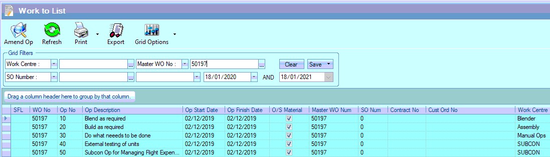 |
This indicates that material(s) that have been marked as required for the job to start have not been issued in full to the WO.
| BOM Notes | This field allows the user to specify specific notes for the part on the BOM. This could be directional notes or instructions but can be used for any notes the user wishes to add. The user also has the option of selecting notes from the Notes Library. This can be accessed by clicking on the |
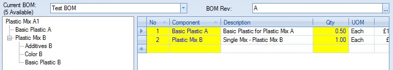
The screen below shows an example BOM with one purchased part and one manufactured part.

Adding New Progress Parts to a BOM
If the user wishes to add a part to the BOM which does not already exist in Progress, they can do this using the ADD NEW PART option.
![]()
Selecting this option will present the user with a new part record for the user to complete.
The user can complete the details of the new part as required.
For more information on creating new parts in Progress, please refer to the Creating New Parts section of the manual.
Once the details have been added, the user can click the ACCEPT option to save the details and then the CLOSE option to return the part to the BOM grid. The user can then specify the BOM quantity required.
Again, once the user has added the part(s) to the BOM, they can save the changes by clicking the ACCEPT option on the BOM screen.
Editing Parts on an Existing BOM
The user also has the ability to make changes to the parts already listed on a BOM. To do this, the user simply needs to click on the part in the “tree view” box on the left hand side of the screen and then click on the EDIT PART option under the BOM grid.
![]()
This will present the user with the inventory record for the selected part.
The user can then make the necessary changes to the part before saving the changes by clicking the ACCEPT option. This will not only save the changes against the inventory record, but will update the BOM screen accordingly. The following shows the updated BOM grid after the purchasing cost was increased for the part shown above.
Deleting Parts on an Existing BOM
The user can remove parts from an existing BOM by selecting the part in question and clicking on the REMOVE PART option.
![]()
The selected part will be removed from the BOM and the screen updated to reflect the change.
Once the user has removed the part from the BOM, they can save the change by clicking the ACCEPT option.
BOM Costs
A summary of costs and times associated with the selected BOM are shown at the bottom of the screen.
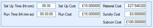
| Set Up Time (hh:mm) | This is the total planned set up time of the routing operations required in the manufacture of one unit of the current part. |
| Run Time (hh:mm:ss) | This is the total planned run time of the routing operations required in the manufacture of one unit of the current part. |
| Set Up Cost | This is the cost of the total planned set up time based on the times and hourly rates entered against the work centres and routing operations. |
| Run Cost | This is the cost of the total planned run time based on the times and hourly rates entered against the work centres and routing operations. |
| Material Cost | This is the total material cost of all purchased parts required for the manufacture of one unit of the current part. |
| Sundry Cost | This is the total cost of all sundry parts required for the manufacture of one unit of the current part. |
| Subcon Cost | This is the total cost of all subcon operations required for the manufacture of one unit of the current part. |
These values and times are reflective of the current BOM and all subsequent BOM levels. Any changes made to the current BOM via the EDIT PART option will result in these values and times being updated accordingly after the change has been saved. If changes are made to the component parts out with the current part’s BOM screen, the user can refresh the values shown using the REFRESH BOM COSTS option, although these values are calculated afresh whenever the part record is opened.
![]()
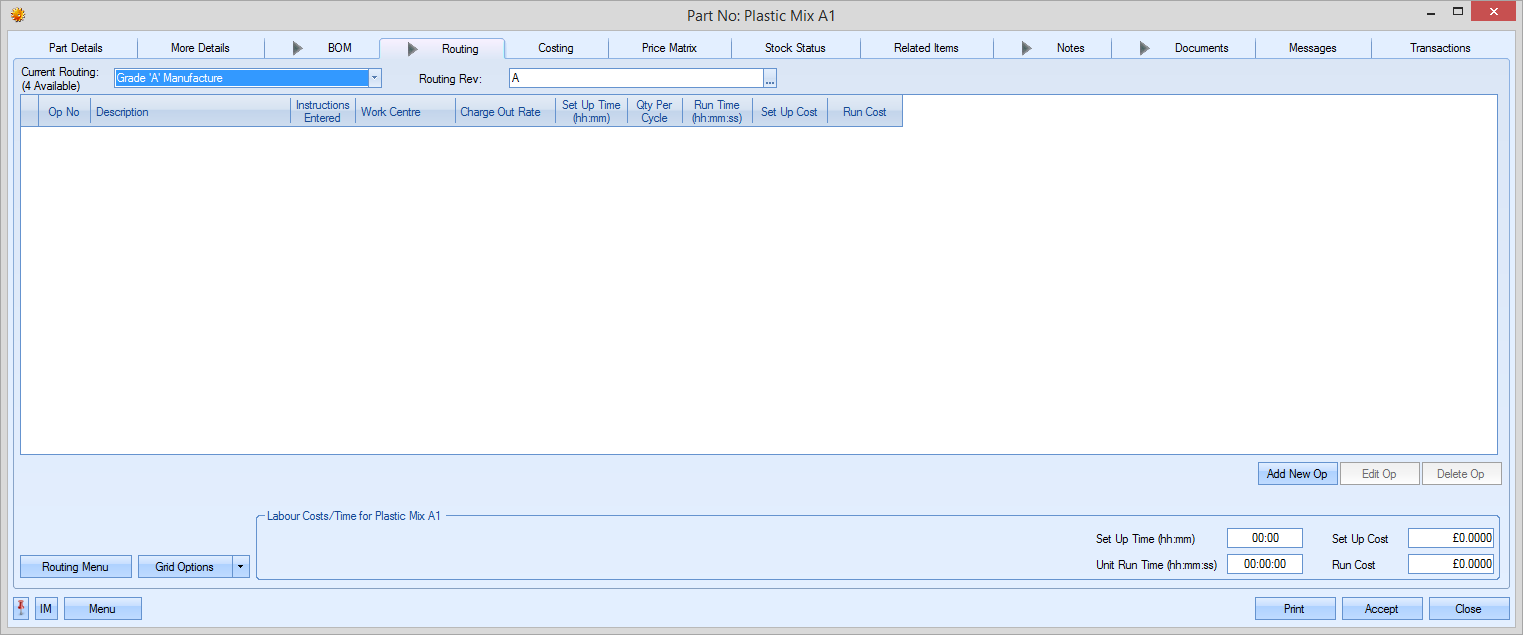
Routing
This screen allows the user to list any internal or sub-contract operations carried out along with the associated work centres in the manufacture of the current part.

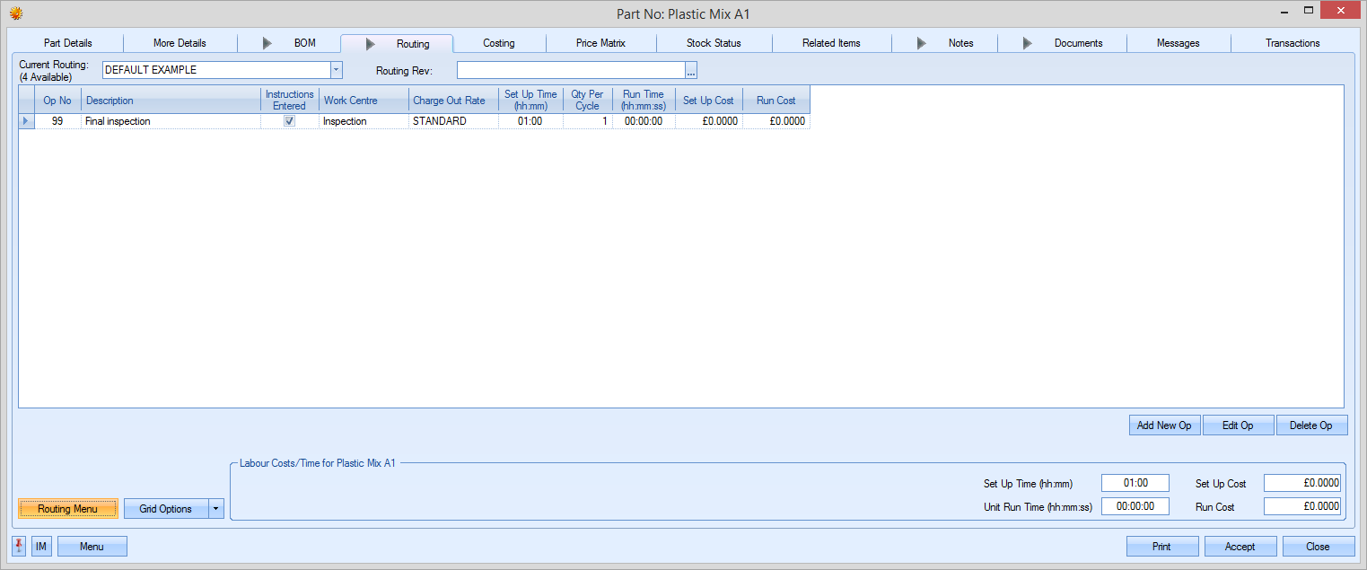
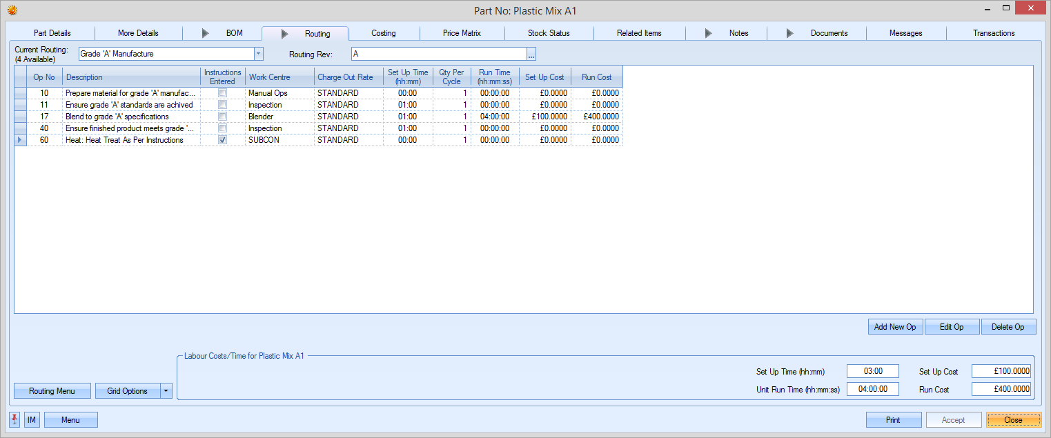
For purchased parts, this screen will be left blank as there will be no operations for a purchased item. For a manufactured part, this screen allows the user to specify one or more operation lists that can be used for the manufacture of the item. An example manufactured part is shown below.
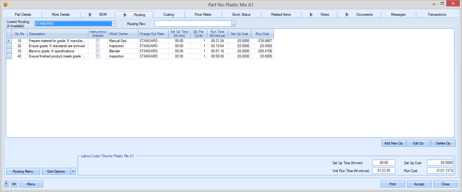
The drop-down list at the top of the screen allows the user to select the routing list to be used for the manufactured part. By default, the first routing is labeled “STANDARD”. Subsequent routings can be labeled however the user desires.
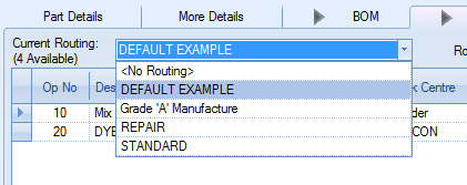
Selecting an alternative routing will result in the details on the screen being updated accordingly as shown below.
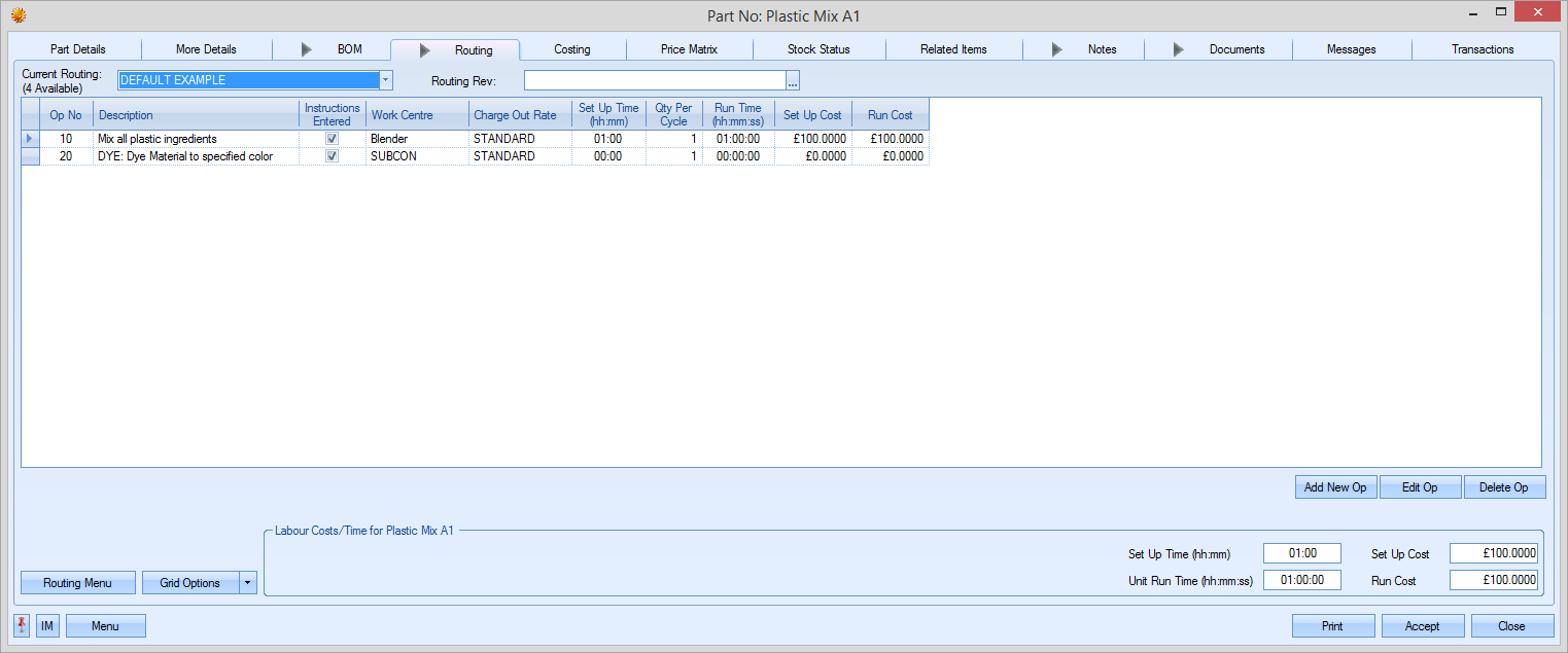
The bottom of the screen has summarised time and cost values for the selected routing.
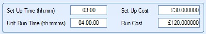
These give the total set up and unit run times and the associated costs based on all the operations listed in the selected routing. Any changes to the routing operations will result in these values being updated to reflect the amended information.
Routing Operations Management
Routing operations, internal or sub-contracted, can be added, amended or deleted from this screen using the options available.
![]()
Adding New Internal Operations to a Routing
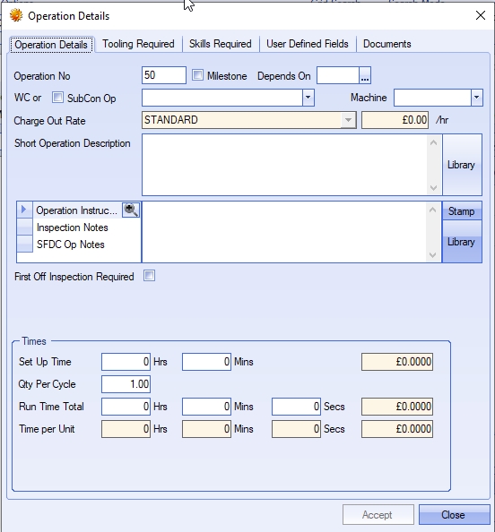
If the user wishes to add an operation to a routing, they can add it using the ADD NEW OP option. Clicking on this option presents the user with the following operation screen.
Operation Details
This tab contains all the main details regarding the operation and either the internal work centre required or the external subcontract requirement.
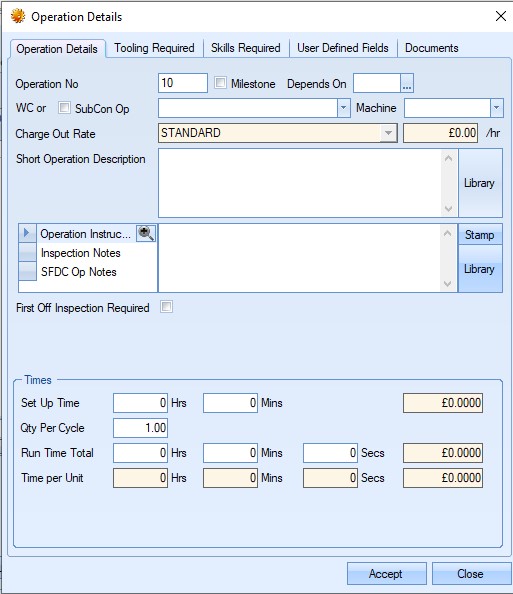
The user can then proceed to complete the information regarding the operation on this screen.
| Operation No | This is the routing operation number. This defaults to 10 for the first operation and then increases in multiples of 10 for subsequent operations, however, this number can be edited by the user. |
| Milestone | This option allows the user to mark the operation as a "milestone" operation. This means the operation has to be marked as "complete" before employees can continue on to subsequent operations. |
| Depends on | This option allows the user to specify dependent operations. This is often referred to as "parallel operations" as it allows different operations to run alongside others or set operation(s) which must be done prior to another operation starting. |
| NOTE: This functionality is not switched on by default. Please contact progress Plus to have this done. |
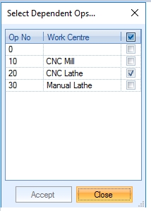
| The easiest way to manage this is to add all the relevent operations to the part's routing and then set the dependencies as required. Clicking this option once the operations have all been added will present the user with a list of operation that the current op can be made dependent on. The user will be presented with a list of current operations. |
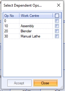
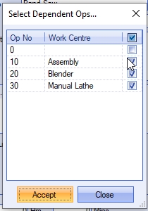
| The user can select the operations the current operation is dependent on. These will be operations that need to be completed before the current operation can be started. |
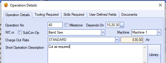
| Once the user has selected the relevant operations, clicking ACCEPT will set the dependencies for the current operation. |
| This process allows the user to set up dependent operations, but also allows them to set up "parallel" operations, where different operations can run alongside each other. In this scenario, you would simply have multiple operations with the same dependencies or starting point. |
| From a planning/scheduling perspective, no dependencies will assume the operations of the routing are sequential, each following the previous op. Using dependencies will schedule the operations accordingly. |
| Example: |
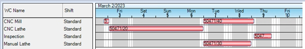
| When no dependencies are set up, the system will automatically sequence the operations based on the operation number. From a scheduling perspective, the system will sequence the ops accordingly. |
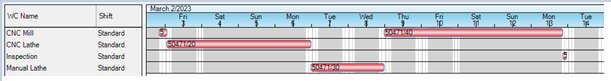
| When dependencies are set, the system will schedule the operations in the way the dependencies have been set. In the example below both operation 30 and 40 are dependent on operation 20. Both these operations will have the following dependency set. |
| When the job is scheduled, the user would see something similar to the following: |
| For more information on planning/scheduling within Progress Plus, please refer to the Shop Floor Loading (SFL) section. |
| WC or SubCon Op | This is where the user specifies whether the operation is an internal or external operation. For internal operations, the user must select the existing work centre associated with the required operation from the drop-down list. |
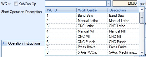
This drop-down list is populated from the Work Centres section of the Maintenance options and lists all work centres currently listed with a LIVE status. For more information on work centres and their creation, please refer to the Maintenance Menu section of the manual.
Once the user selects an existing work centre for an internal operation, the work centres, the associated hourly rate is displayed to the right of the work centre drop-down list.
![]()
| Short Op. Description | This field allows the user to provide a short operation description regarding the operation. The user has the option of choosing a description from the Notes Library section of Progress, or manually entering the details. |
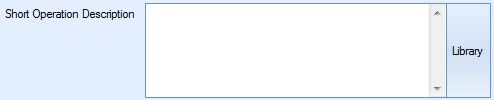
If the user manually enters a description not currently held in the Notes Library, Progress will prompt the user
To use the Notes Library, the user can click on the LIBRARY option. This will present the user with the Notes Library window, from which they can choose the required description. For more information on using the Notes Library section of Progress, please refer to the Notes Library section of the manual.
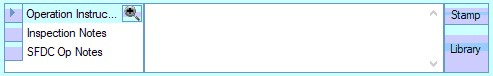
| Operation Instructions | This field allows the user to enter more detail instructions relating to the operation. This note will copy across to the WO operation whenever a WO is created. Again, the user has the option to select notes from the Notes Library if they require, or manually enter the details. To use the Notes Library, the user can click on the LIBRARY option. This will present the user with the Notes Library window, from which they can choose the required description. For more information on using the Notes Library section of Progress, please refer to the Notes Library section of the manual. |
| Inspection Notes | This field allows the user to enter inspection notes against a specific operation. This note will copy across to the WO operation whenever a WO is created. Again, the user has the option to select notes from the Notes Library if they require, or manually enter the details. To use the Notes Library, the user can click on the LIBRARY option. This will present the user with the Notes Library window, from which they can choose the required description. For more information on using the Notes Library section of Progress, please refer to the Notes Library section of the manual. |
| SFDC Op Note | This field allows the user to enter specific SFDC notes against a specific operation. This note will copy across to the WO operation whenever a WO is created. When the employee jobs onto the operation via the SFDC station, the note is displayed on screen for the employee to see. The employee also has a NOTES option that allows them to expand the note to see if in full. |
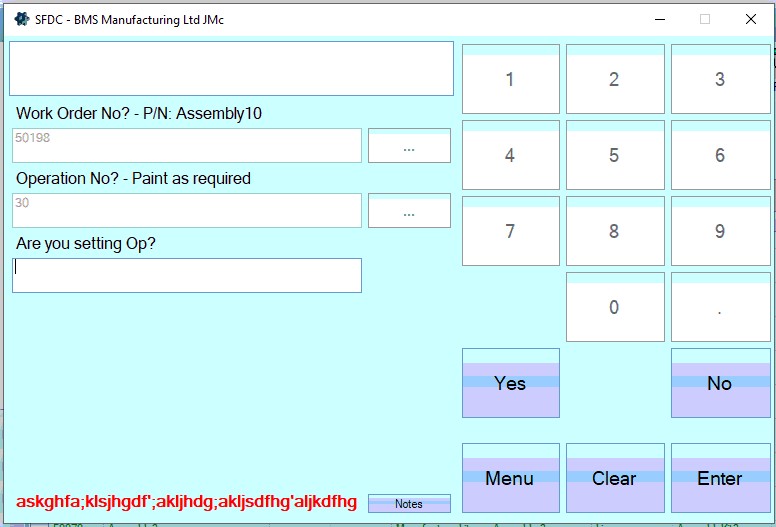
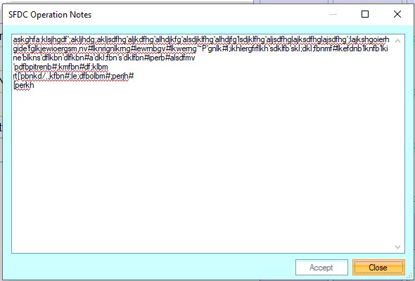
Again, the user has the option to select notes from the Notes Library if they require, or manually enter the details. To use the Notes Library, the user can click on the LIBRARY option. This will present the user with the Notes Library window, from which they can choose the required description. Formore information on using the Notes Library section of Progress, please refer to the Notes Library section of the manual.
| Set Up Time | These fields allow the user to specify the set up time in hours and minutes for the operation. This is the initial set up or preparation time required before the operation can start. |
![]()
Once the user enters a time, Progress calculates the associated cost based on the work centre’s hourly rate. An example is shown below.
Work Centre: BLENDER Hourly Rate: £30 p/h
![]()
| Qty Per Cycle | This field allows the user to specify the number of units that can be done in a single run time period. |
![]()
| Run Time Total | This is the total run time required to produce the quantity specified in the Qty Per Cycle field above. The user can enter the run time in hours, minutes and seconds |
![]()
Once the user enters a time, Progress calculates the associated cost based on the work centre’s hourly rate. An example is shown below.
| Work Centre: BLENDER | Hourly Rate: £30 p/h |
![]()
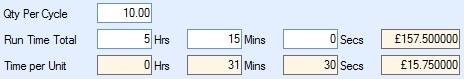
| Time Per Unit | These fields are calculated based on the Qty Per Cycle and Run Time Total values entered by the user. These fields show the individual run times per unit. Typically, where the Qty Per Cycle has a value of 1, the Run Time Total and Time Per Unit will match. |
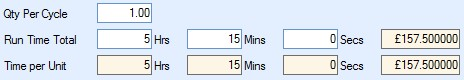
Where the Qty Per Cycle has been entered as a value greater than one, Progress will calculate the run time per unit and display it in these fields.
Once all the details have been entered, the user can save the new operation by clicking the ACCEPT option. The user will be returned to the routing screen with the new operation now displayed in the operations list.
Adding New External Operations to a Routing
If the user wishes to add a sub-contract operation to a routing, they can add it using the ADD NEW OP option. Clicking on this option presents the user with the following operation screen.
The user can then proceed to complete the information regarding the sub-contract operation on this screen.
| Operation No | This is the routing operation number. This defaults to 10 for the first operation and then increases in multiples of 10 for subsequent operations, however, this number can be edited by the user. |
| WC or SubCon Op | This is where the user specifies that the operation is a sub-contract operation. For sub-contract operations, the user must tick the SubCon Op tickbox. This changes the drop-down list from a list of internal work centres to a list of external sub-contract codes. |
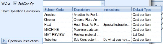
This drop-down list is populated from the Sub-Contract Codes section of the Maintenance options and lists all sub-contract codes currently listed with a LIVE status. For more information on sub-contract codes and their creation, please refer to the Maintenance Menu section of the manual.
Once the user selects the sub-contract code required, the operation screen changes to accommodate the details of the sub-contract requirement.
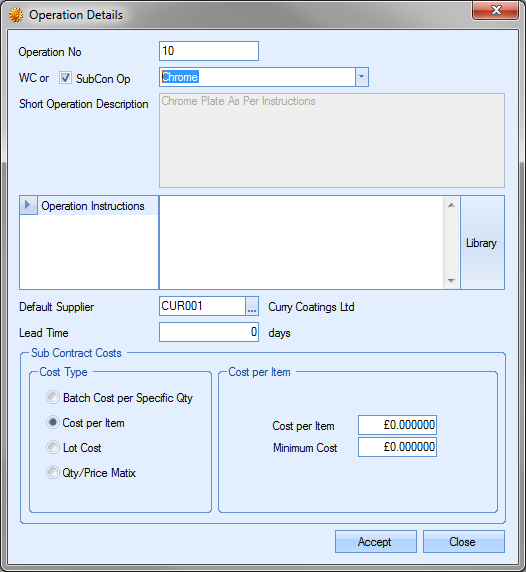
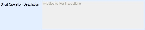
| Short Op. Description | For sub-contract operations, this field defaults to the description entered against the selected code in the Sub-Contract Code record. This field cannot be changed by the user. |
| Operation Instructions | This field allows the user to enter more detail instructions relating to the operation. If specific instructions have been recorded against the sub-contract code, these will be pulled through from the sub-contract code record. Again, the user has the option to select notes from the Notes Library if they require, or manually enter the details. |
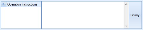
To use the Notes Library, the user can click on the LIBRARY option. This will present the user with the Notes Library window, from which they can choose the required description. For more information on using the Notes Library section of Progress, please refer to the Notes Library section of the manual.
| Default Supplier | This field allows the user to specify the supplier who will carry out the sub-contract task. If a supplier has already been specified against the sub-contract code, this will be pulled through to the operation screen. The user can specify the supplier if known at this stage or can leave this blank for the supplier to be specified at the purchase order stage. |
![]()
| Lead Time | This field allows the user to specify the lead time of the sub-contract operation. If the lead time is specified against the sub-contract code, this field will default to that lead time. The user can change this value if a different lead time is to be applied. |
![]()
| Sub Contract Costs | The next section allows the user to specify how the sub-contract operation is to be costed. The user has 4 options available to choose from. |
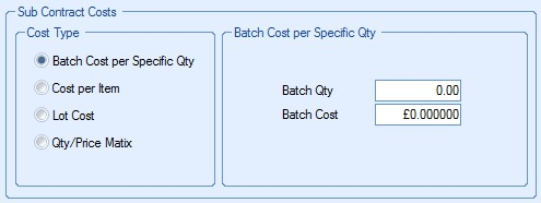
| Again, the costing method will default to the selection made against the sub-contract code, but can be changed if necessary by the user. The options available are as follows: |
Batch Cost per Specific Qty This option permits the user to enter a batch size and cost for that specific batch. The following example has a Batch Qty of 50 and a Batch Cost of £20.
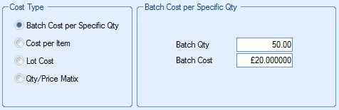
If the user were to send a batch of 200 items for subcontract work the cost would therefore be £80 (200/50 x £20).
| Cost Per Item | This option allows the user to enter a cost per item for the sub-contract cost and can be used in conjunction with a specified minimum order quantity. The following example has a Cost Per Item of £1.25 with a minimum charge of £75. |
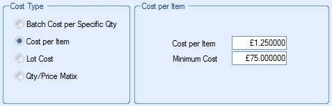
The system would cost any quantity up to 60 (£75/£1.25 = 60) as costing the minimum charge of £75 i.e. to plate 1 item = £75, 15 = £75, 42 = £75 etc as these quantities do not fulfil the minimum charge. Any quantity greater than 60 would be costed at Minimum Charge + Cost per Item e.g. a quantity of 80 would be costed at £100 (£75 + 20 x £1.25).
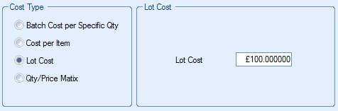
| Lot Cost | This option allows the user to enter a single cost for the sub-contract requirement. This is used when a fixed fee has been agreed with the supplier. The example below shows a fixed fee of £100. This would be the same whether the quantity being sub-contracted was 1 or 1000. |
| Qty/Price Matrix | This option allows the user to record price breaks against different quantities. |
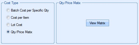
The user can add the price breaks for this sub-contract operation by clicking on the VIEW MATRIX option. The user will then be presented with the following screen.
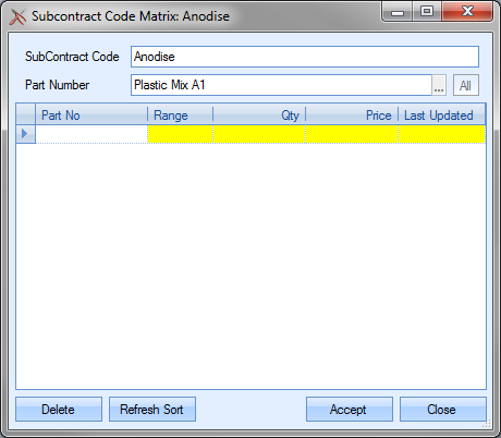
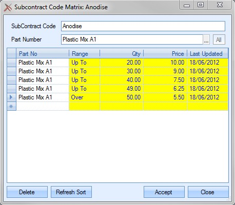
The user may then click onto the Range field (in yellow) and choose either “Over” or “Up To”. A “Qty” and “Price” each may also be entered into the appropriate yellow fields. An example is shown below.
e.g. for a Qty (quantity) “Up To” 10, the Price is £10.00 each,
for a Qty (quantity) “Up To” 20, the Price is £9.00 each, etc
until a maximum quantity is reached e.g. 49. The user may then choose the “Over” option from the Range field i.e. any quantity required greater than 49 would cost £5.50 as shown in the next screen.
If any price breaks are entered in error, the user can delete them by highlighting the erroneous entry and click the DELETE option. The user will be prompted to confirm the deletion.
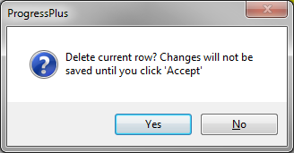
Clicking YES will complete the deletion. Clicking NO will return the user to the Matrix screen.
The REFRESH SORT option allows the user to refresh the entries by quantity sequence. This can be used after changes have been made to reorder the information entered.
![]()
Once the user has made the required changes, they can save the changes by clicking on the ACCEPT option. The costing of the sub-contract operation would then use the price matrix details entered for calculating the planned costs associated with the sub-contract operation.
| Once all the details have been entered, the user can save the new operation by clicking the ACCEPT option. The user will be returned to the routing screen with the new sub-contract operation now displayed in the operations list. |
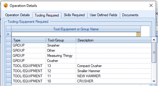
Tooling Required
NOTE: This section is only available if Progress has the additional Quality module.
This section allows the user to specify specific tooling required for the operation. The user can select the tools/equipment from the list set up in the Quality > Tooling & Equipment section.
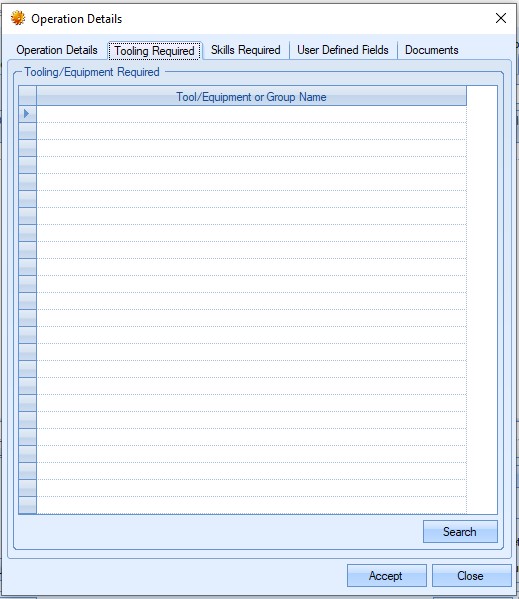
The user can select the tools required for the operation using the drop-down list. The user can select a specific tool or a group of tools for the operation.
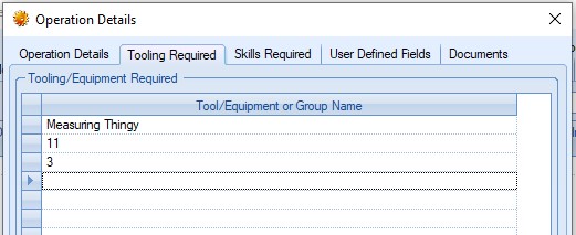
Once the required tools/tool groups are selected, the user can save the information by clicking ACCEPT. This information will default to any work orders that are created for the part number and feed into the Tooling & Equipment Issue/Return functionality that's available.
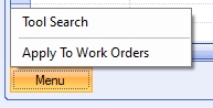
The user also has the ability to select multiple tooling for addition to the routing operation. This can be done via the MENU > TOOL SEARCH option.
Selecting this option will present the user with a list of all tools to select from.
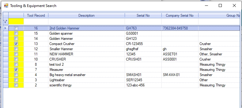
The user can tick multiple tools to be added from the list. Clicking ACCEPT will add all the selected tooling to the routing operation.
The user also has the ability to push any changes to the routing operation's tooling to any existing work orders. This can be done via the MENU > APPLY TO WORK ORDERS option.
Selecting this option will display a list of all work orders for the current part number.
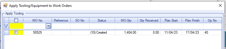
Again, the user can tick individual work orders, or click the column heading to select all work orders listed. Clicking ACCEPT will update all the selected work orders with the new part routing tooling.
Skills Required
This section allows the user to specify any particular employee skills required for the operation. Setting skills against the operation ensure only employees with the correct skills can carry out the operation.
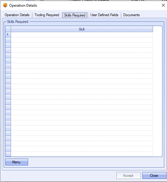
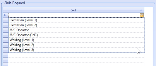
Skills can be added manually to the operation using the drop-down list.
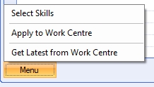
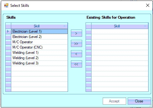
They can also be added via the MENU > SELECT SKILLS option.
This presents the user with a list of all skills and allows them to be added/removed individually or as multiples, using the single and double arrows respectively.
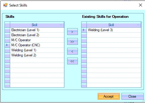
Once selected, the user can click ACCEPT to add the selected skills to the routing operation.
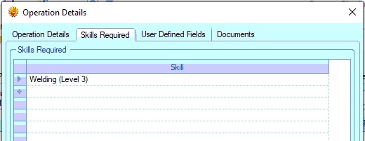
Once all skills have been added, clicking ACCEPT will save the skills. These skills will then become a default requirement of the employee to ensure only the correct employees carry out the operation.
Updating Master Work Centre Skills
The user also has an option to update the master work centre with the currently selected skills. This can be useful if the requirements have been update on the part and are now to be the default set of skills for the work centre. THis can be done via the MENU > APPLY TO WORK CENTRE option.
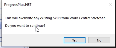
Selecting this, the user will be asked to confirm the updating of the work centre.
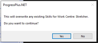
Clicking YES will proceed to update the master work centre. Clicking NO will return the user to the part routing.
Updating Existing Work Orders
The user also has an option to update the current operation with the part routing operation work centre's current skills. This is useful if the master work centre has been updated and the current part also needs to be update. This can be done via the MENU > GET LATEST FROM WORK CENTRE option.
Clicking this option will prompt the user to confirm the updating of the skills from the master work centre.
Selecting YES will update the current part routing operation with the latest skills set in the master work centre record. Selecting NO will stop the uipdate and return the user to the operation skills.
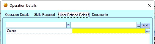
User Defined Fields
This section allows completion of any user-defined fields (UDFs) set up against routing operation.
For more information on setting up UDFs, please refer to the Maintenance > User Defined Fields section of the manual.
Documents
This section allows the user to add documents, files, images, etc. to the routing operation.
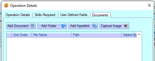
The options allow the user to add individual documents, specific folders, hyperlinks or captured images on suitable devices to the operation. Once all items have been added, the user should click ACCEPT to save them.
NOTE: To ensure all employees are able to access the attached items, the user should ensure these are saved to a suitable shared location, have internet access, etc. otherwise the items might not be accessible.
Editing Existing Routing Operations
The user can edit any existing operations by clicking on the EDIT OP option.
![]()
This presents the user with the operation details screen as described above. The user can then make any changes required. Once the changes have been made the user can click the ACCEPT option to save the changes.
Deleting Routing Operations
The user can remove any existing operations from the routing by highlighting the operation to be removed and clicking on the DELETE OP. This will remove the operation from the routing list.
![]()
Once any changes have been made to the routing screen, the user can click the ACCEPT option to save the changes made.
Routing Management
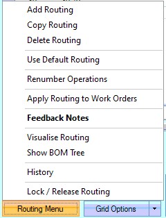
Manufactured part’s routings can be created, copied, amended or deleted from this screen using the various options. The ROUTING MENU option at the bottom left of the screen contains several options to allow the user to create new routings, copy existing routings from other manufactured parts, set the routing to the system default routing or delete existing routings as well as renumber existing routing operations.
Add Routing
The user can create additional routings for the selected part by clicking on the ADD ROUTING option. When selected, the user is asked to provide a name for the new routing.
The name provided can be anything, but it’s often used to indicate the purpose of the additional routing; a customer reference or reference the reason for the alternative, i.e. Repair, or reference to the material that is used in the manufacturing process. Once entered, the routing screen is updated with the new routing name which, by default, will be blank. The user can then add the routing operations required. The new routing name can also be seen in the CURRENT ROUTING drop-down list at the top of the screen too.
To add new operations to a routing, the user can click on the ADD NEW OP option immediately under the grid to add new operations. For more information on adding operations to a routing, please refer to the Routing Maintenance section of this manual.
Copy Routing
This option allows the user to copy an existing routing from another part in Progress. This is particularly useful when large-scale routings are used and there are similarities between manufactured items. When the user selects the COPY ROUTING option, the following screen is displayed.
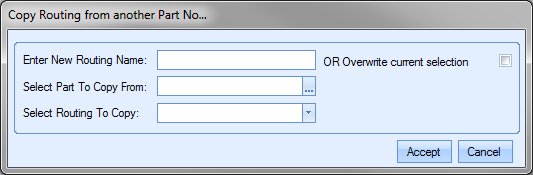
The user can choose to create a new routing by entering a name for the new routing or overwrite the currently selected routing by ticking the overwrite option. The user must then select the part number that has the required routing. They can do this by clicking on the ![]() option at the end of the field. This will present the user with the Inventory Search window. The user can then search for the part number required.
option at the end of the field. This will present the user with the Inventory Search window. The user can then search for the part number required.
Once the user has identified the part required, clicking the SELECT option will return the part to the COPY ROUTING screen.
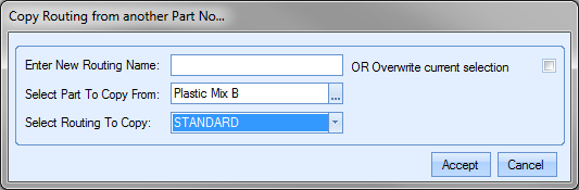
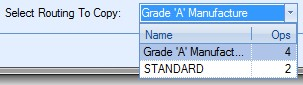
Finally, the user can select the routing required using the drop-down list.
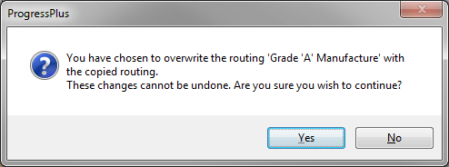
Once selected, clicking the ACCEPT option prompt the user to confirm the change before pulling the BOM details through to the BOM screen.

The user can now make additional changes to the routing operations to fine tune if required. Once finalised, the user must click the ACCEPT option to save the new routing details. The new routing is now ready for use.
Use Default
This option allows the user to update the current routing to that of the system default routing. If all manufactured items have similar operations or share common operations, a default routing incorporating these can be created to provide the user a quick means of adding these operations into routings. A default routing is created within the system options under the Miscellaneous & Inventory options.
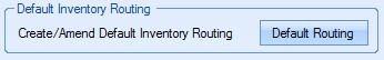
For more information on creating a default routing, please refer to the Default Inventory Routing section of the system options.
When the user clicks on the USE DEFAULT option, they are prompted to confirm whether a new routing is being created or whether they are updating the currently selected routing.
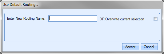
Once the user had decided how they wish to proceed, clicking the ACCEPT option, the routing screen is updated. If a new routing was entered, the routing screen displays the new routing with the default routing operations listed. If the user chose to overwrite the existing routing, the existing routing is updated to show the default routing operations.
The user can now make any additional changes to suit their requirements or simply click the ACCEPT option to save the routing operations.
Delete Routing
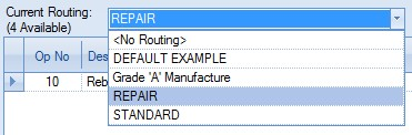
This option allows the user to delete existing routings from the manufactured part. This option could be used if older routings have become obsolete and the user chooses to remove them from the part. To delete a routing, the user must firstly select the routing from the drop-down menu at the top.
Once the routing to be deleted has been selected, the user can click the DELETE ROUTING option. The user will be prompted to confirm the deletion.
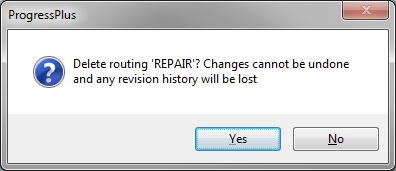
Once the user confirms, the routing information will be cleared from the screen and the part will default to the <NO ROUTING> option.
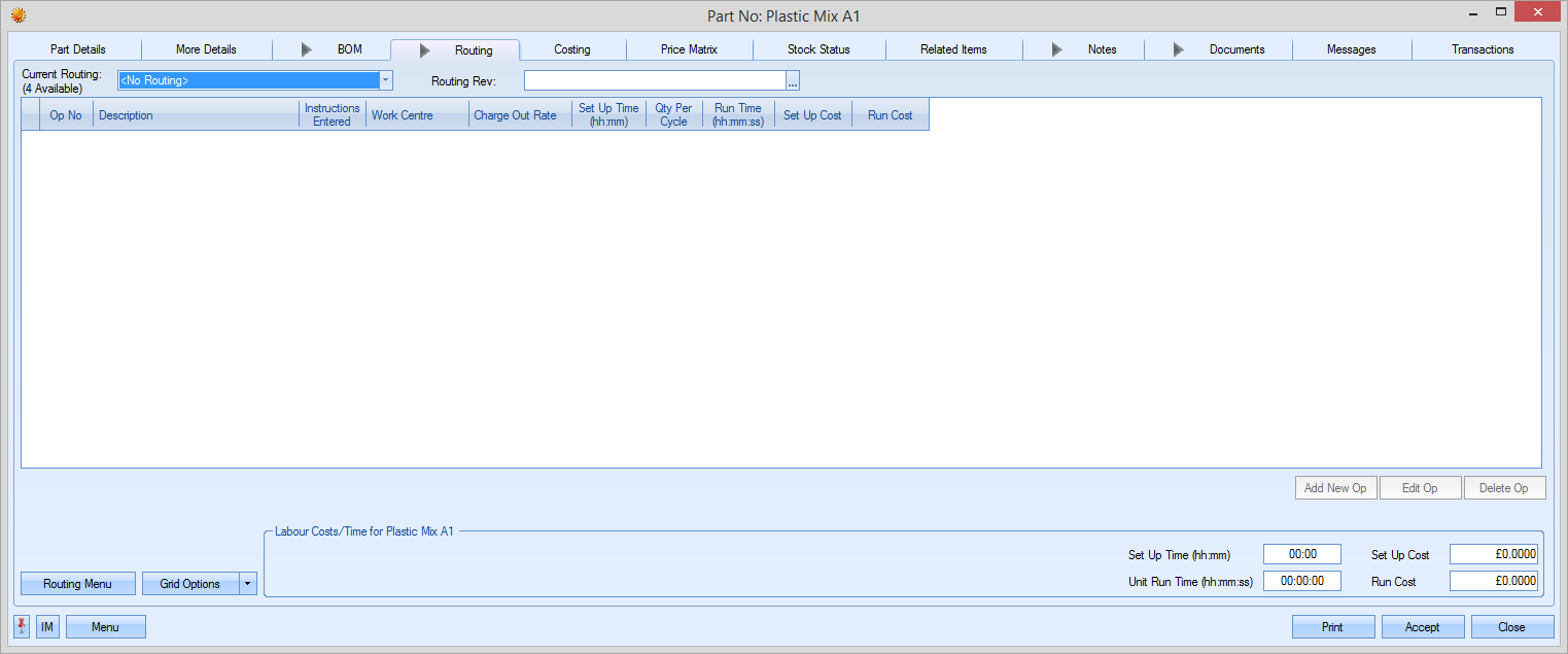
The user can now select the routing the wish to use going forward from the drop-down list at the top of the screen or create a new routing if required. Again, clicking the ACCEPT option will save the changes made.
Renumbering Operations
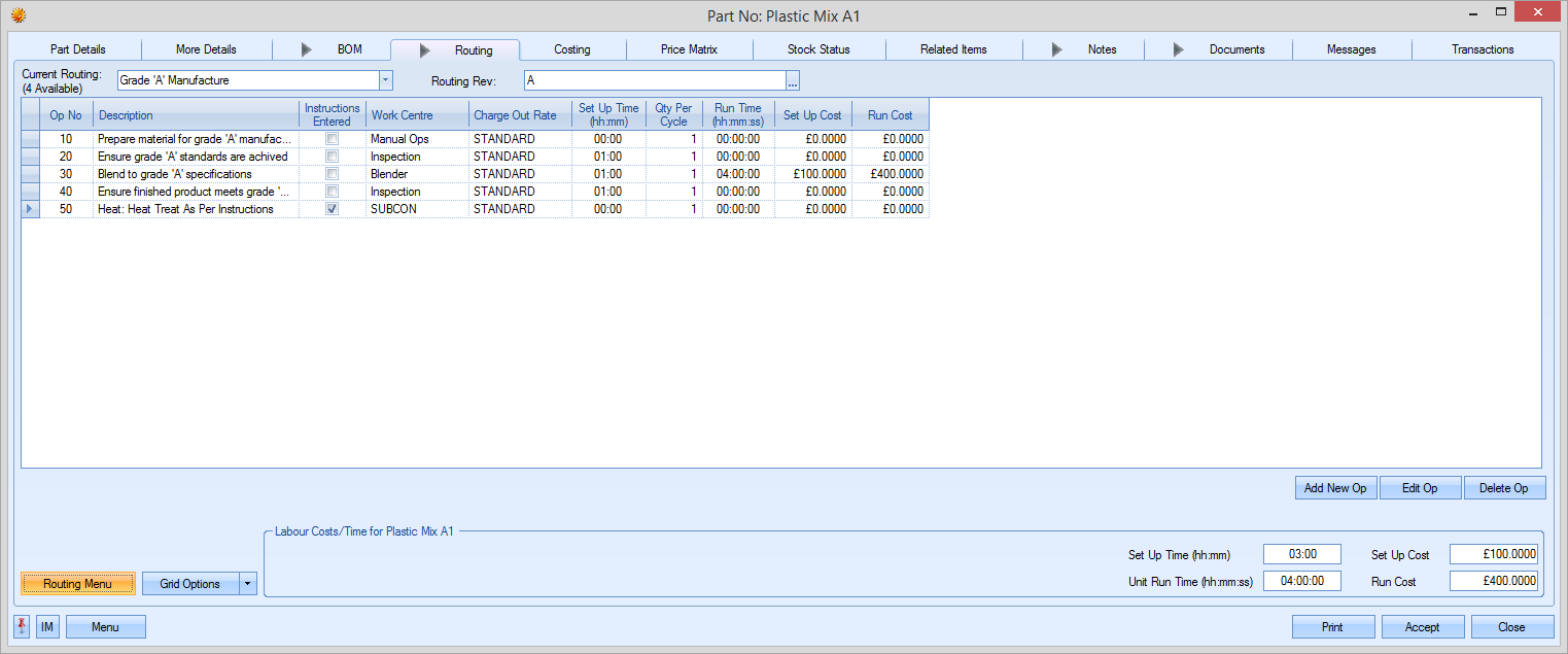
The user has the option of "tidying up" the operation numbers of the selected routing. This option resets the listed operations in a 10, 20, 30... sequence. This can be useful if the selected routing has been edited to add new operations in between existing operations.
Selecting the RENUMBER OPERATIONS option results in the following:
Apply Routing to Work Orders
This option allows the user to push amendments to routings to existing WOs. The user will be prompted to select the WOs to be updated as shown below.
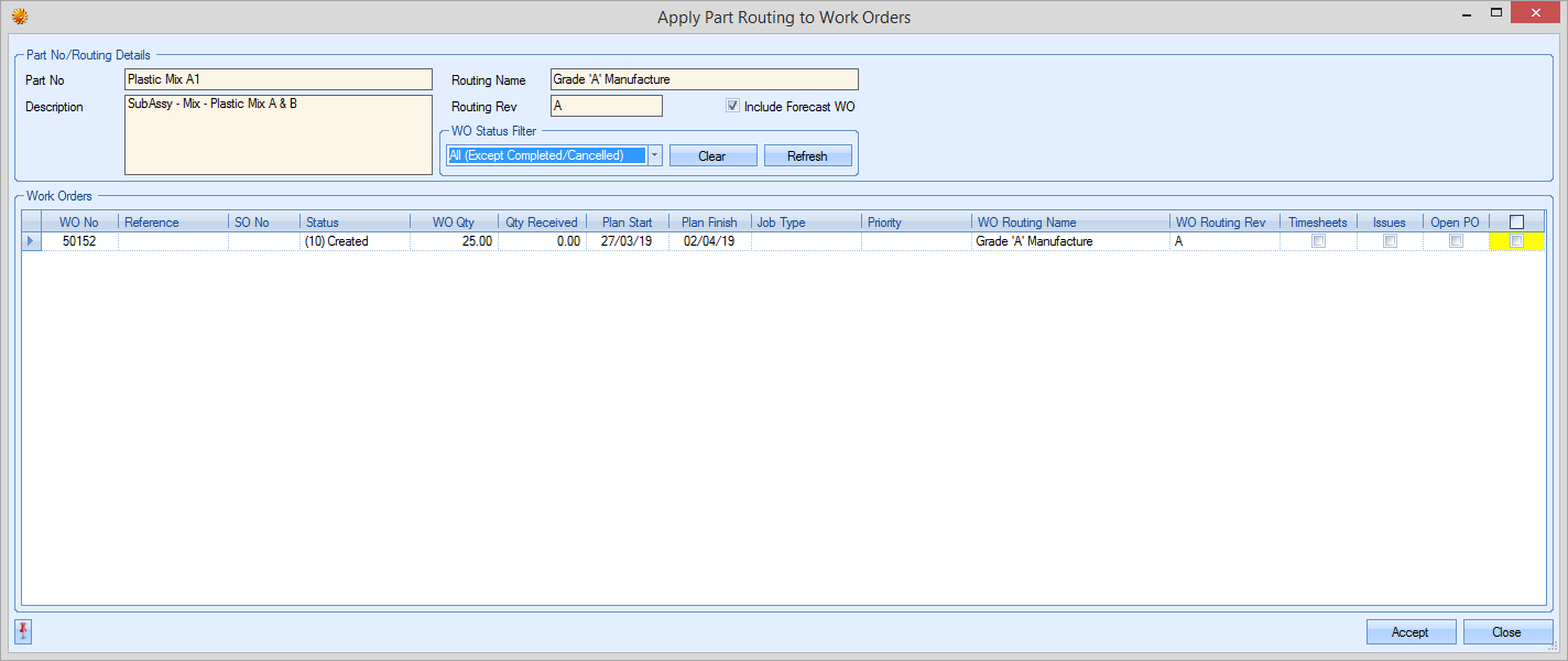
The user can use the status filter to narrow down the list of WOs that are to be updated. By default, the system will suggest all WOs (except cancelled or complete WOs), although this can be changed. Clicking REFRESH will update the list of WOs shown.
Once the user has selected the WOs to be updated, clicking ACCEPT will prompt the user to confirm the update before updating the selected WOs.
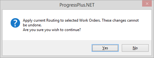
Feedback Notes
This option displays any feedback notes that have been recorded against any operations on work orders for the current part. This option is only available if feedback notes have been entered against any WO operation and provides a convenient method of seeing all these notes together.
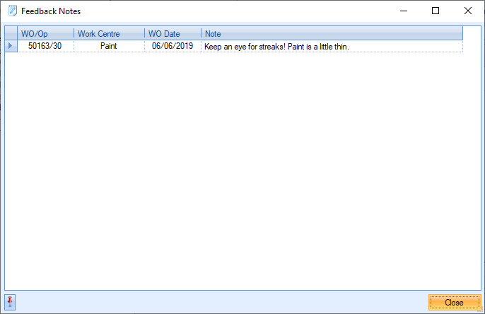
Show BOM Tree
This option allows the user to view operations of sub-assembly parts contained in the BOM without the need to drill into the sub-assembly part itself. This option adds a similar tree view to the BOM tab as shown below.
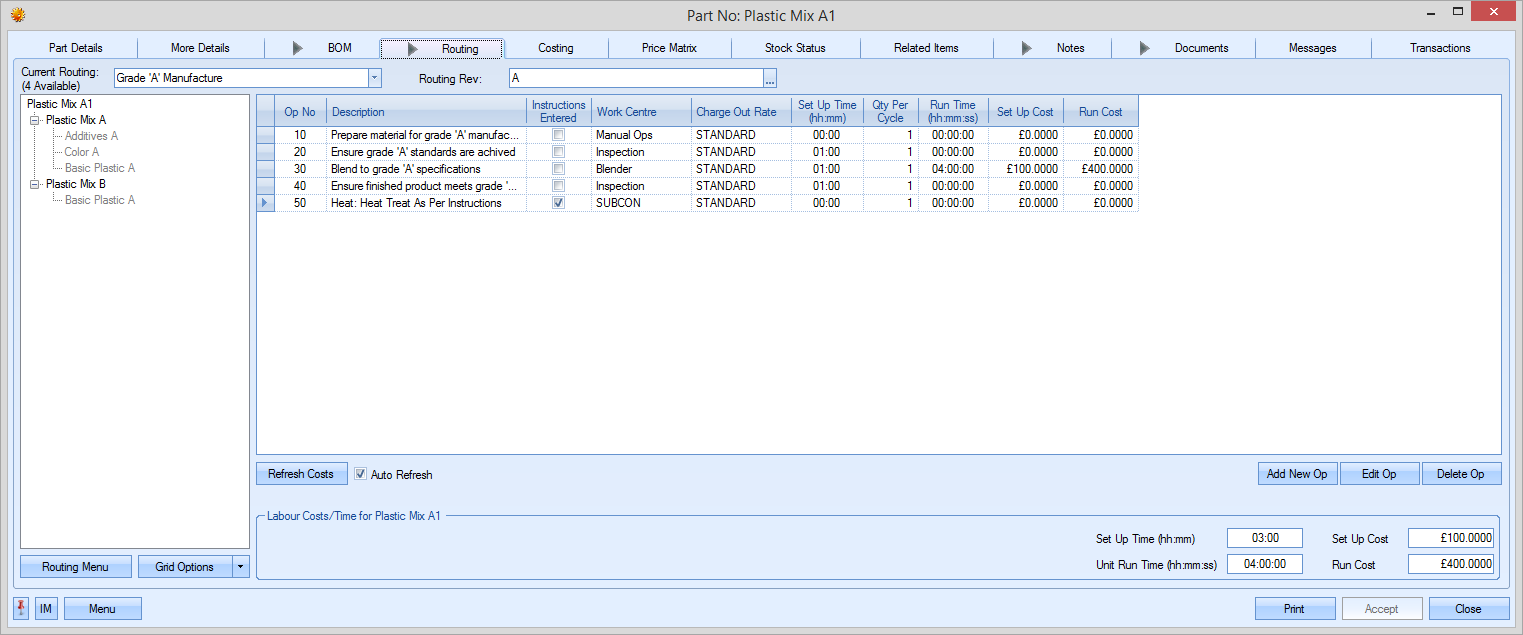
Each manufactured part on the BOM tree is highlighted. Selecting any of these will result in the routing ops for the selected part being displayed on screen for the user to see as shown below.
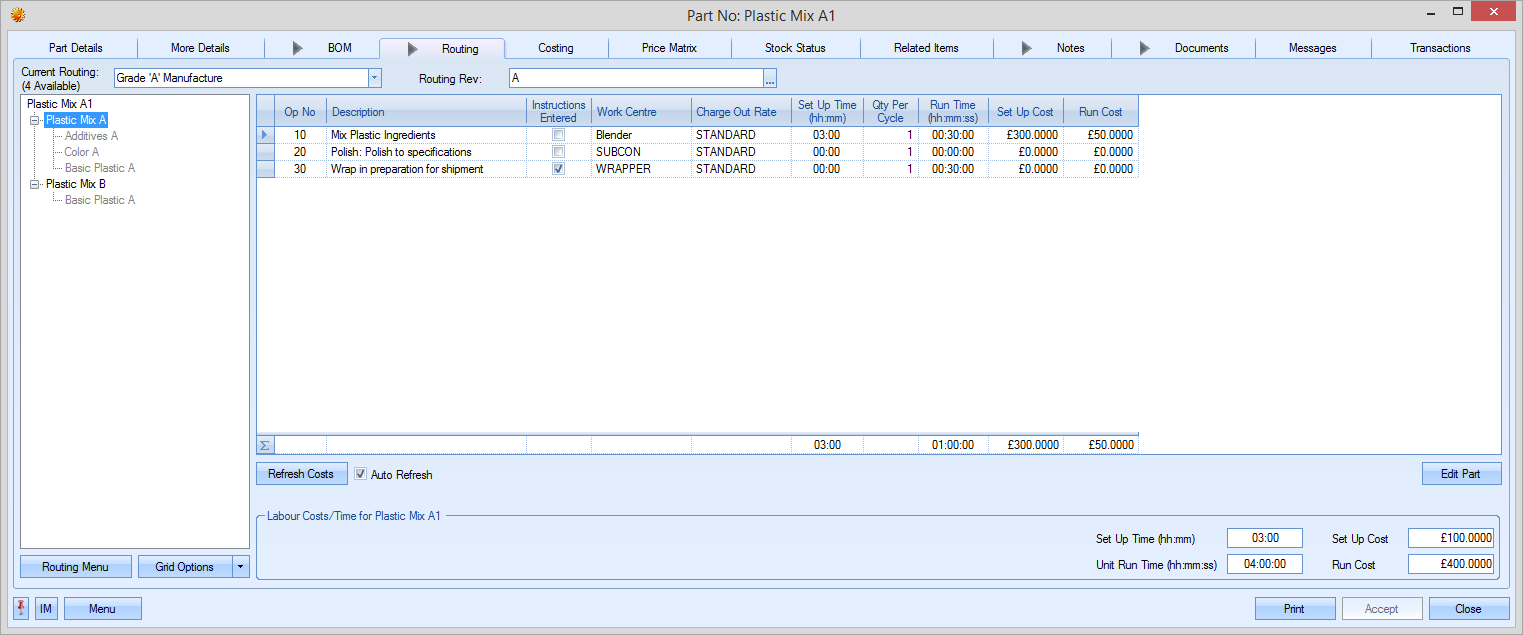
Unticking this option will show only the immediate operations of the current part number.
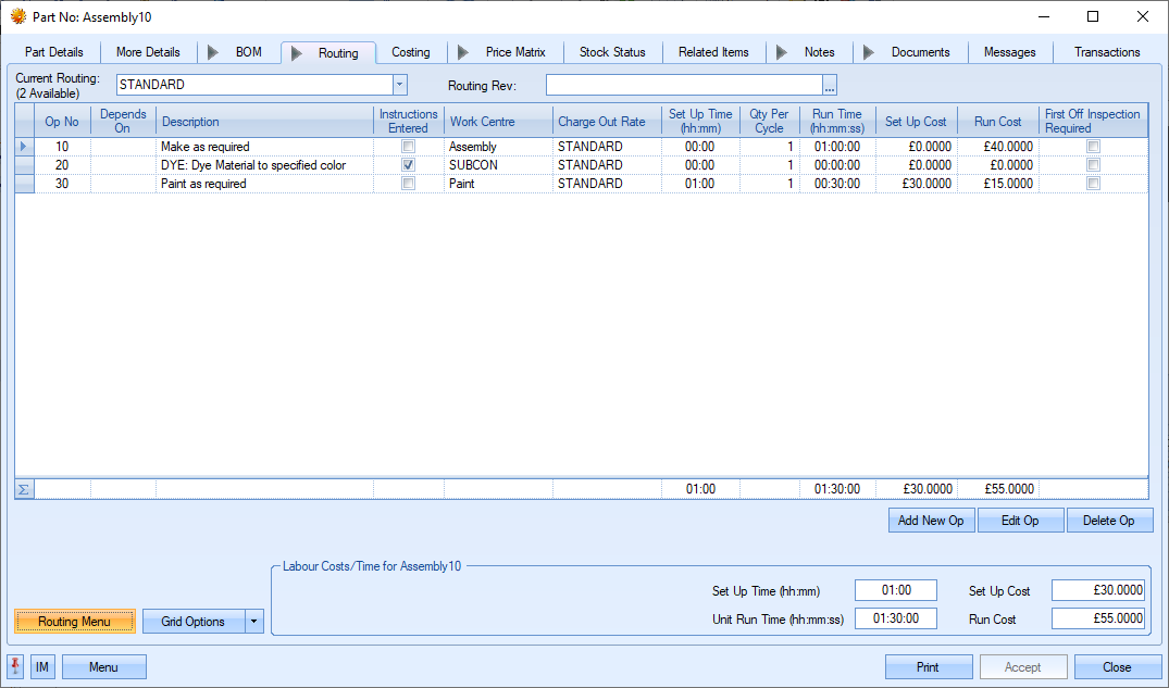
Visualise Routing
This option generates a visual representation of the current part's immediate routing. Using the work centre and subcontract lead times, the user is presented with a screen showing the operations and how they interact with each other. Primarily designed for use when using parallel operations, the screen shows which operations are dependant on others as well as informs the user of the total number of days to complete and the earliest finish date based on the current date. The screen shot below shows an example of a standard sequential routing where each operation is dependant on the previous operation.
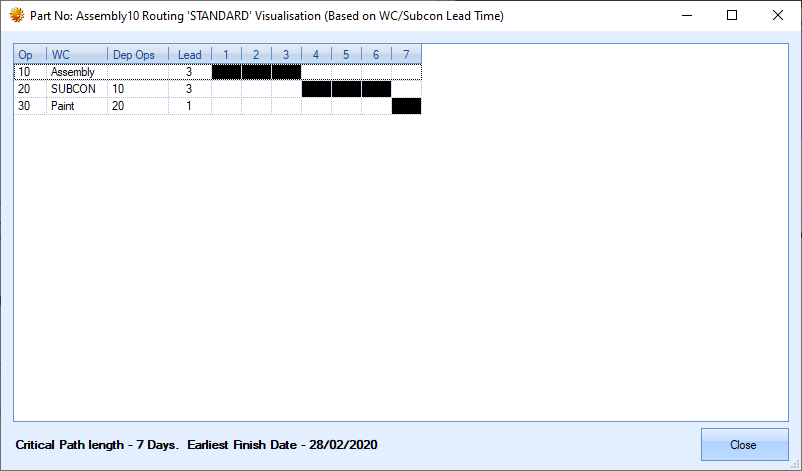
Using parallel operations allows multiple operations to run along side each other. This is often used when two or more aspects of a job can be worked on at the same time. An example of this is shown in the screen shot below.
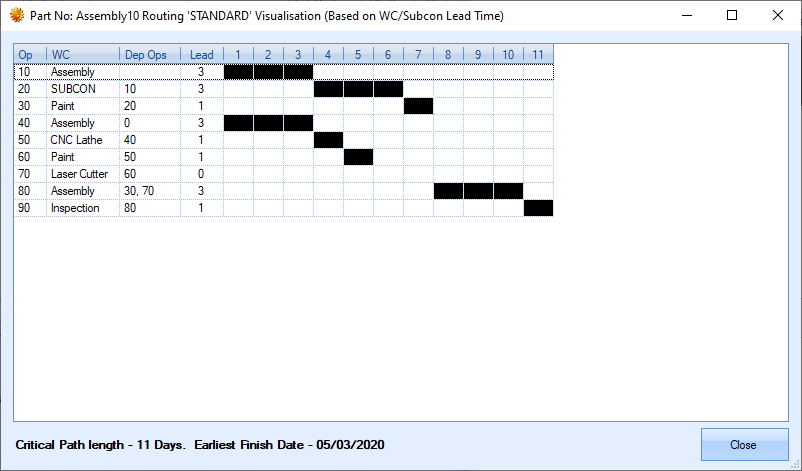
As can be seen above, operations 10 and 40 can start at the same time with both processes having their own dependent operations, however, operation 80 requires all these previous operations to be complete before it can start.
History
This option shows a historical summary of the current part and the selected routing.
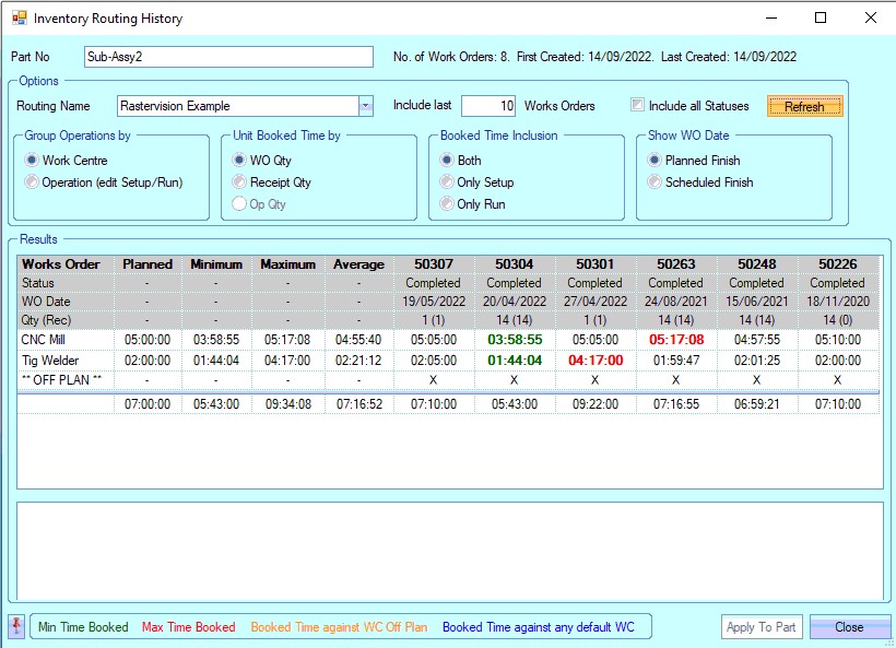
The user can see the history of the part and its routings across a number of work orders, including the individual times against each of the planned operations. By default, only completed work orders are shown, although the user can tick the INCLUDE ALL STATUSES option if they wish to include work orders at other statuses.
Any time recorded against work centres/operations that are not part of the planned routing is shown as ** OFF PLAN **. Highlighting any cell also shows any associated timesheets at the bottom of the screen so the user can see where this information comes from.
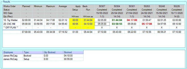
The screen also summarises the maximum, minimum and average times across the operations or work centres. The coloured legend at the bottom of the screen indicates what each of the highlighted colours represent.
The user has a variety of options available to them in how they wish to view this info; it can be viewed by work centre or by operation (shown below), but can also be restricted to setup time or run time if necessary.
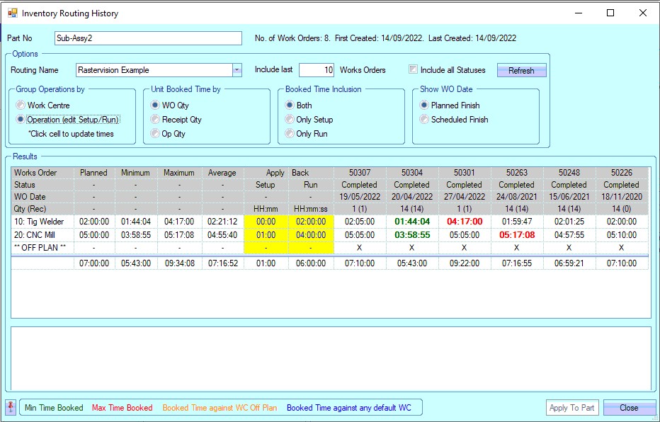
When viewing the routing history by operation, the user can also update the existing planned routing based on the previously recorded times. The APPLY BACK values are those that will be applied to the existing routing. These values can be manually set, or set based on selection of previous times.
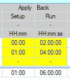
The user can set the APPLY BACK times based on previous work order performance by selecting the time shown against any previous work order.
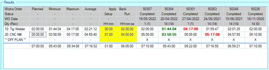
(BEFORE: APPLY BACK shows the existing planned routing times)
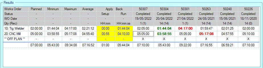
(AFTER: APPLY BACK shows the new times after selecting the 50304/10 time and the 50307/20 time)
If the user is only looking at set up or run time (Booked Time Inclusion options), the same can be applied, but only thee selected type's times will be selected and updated. The example below shows the result when only SETUP TIME is being considered.
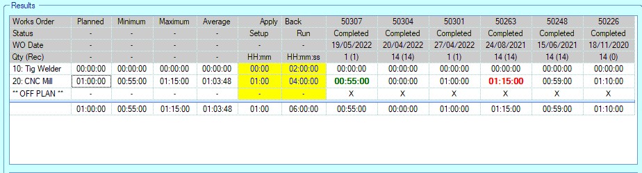
(BEFORE: APPLY BACK shows the existing planned routing times)
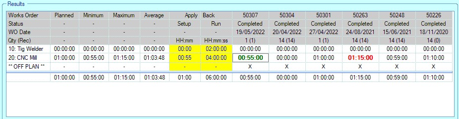
(AFTER: APPLY BACK shows the new Op 20 set up time after selecting the 50307/20 time)
Once the new times have been set, the user can update the existing planned routing with the new times by clicking the APPLY TO PART option at the bottom of the screen. Once done, the planned routing will reflect the selected times.
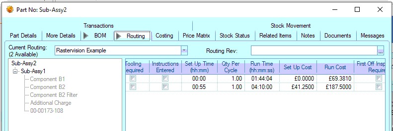
Lock/Release Routing
This option allows permitted users to lock a routing so it cannot be edited. This is a user permission and is set against the user's access permissions in the Admin section of progress. This option will only be available to users who have this permission. When a routing is locked, a small padlock icon will be displayed against the routing tab to indicate such. The routing can be viewed but cannot be edited until its unlocked by an authorised user.
![]()
Routing Revisions
The user can record revision history against each routing in the system using the Routing Revision field at the top of the screen.
![]()
The user can record revisions against the routing by clicking on the ![]() option at the end of the field. This will present the user with the following screen.
option at the end of the field. This will present the user with the following screen.
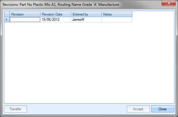
The user can record the revision ID and any notes associated with the revision. The date will default to the current date and the user to the current Progress user. Once the details have been added, the user can select the revision by highlighting the required revision and clicking on the TRANSFER option. This will return the user to the routing screen and attach the selected revision.
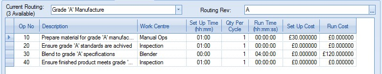
Once the user has added a revision to the routing, they can save the changes by clicking the ACCEPT option. Additional revisions can be added and selected as and when required.
Costings
After the basic part information as described above has been entered, the user may wish to see some detailed costing information relating to this item. The user can do this on the Costing screen.
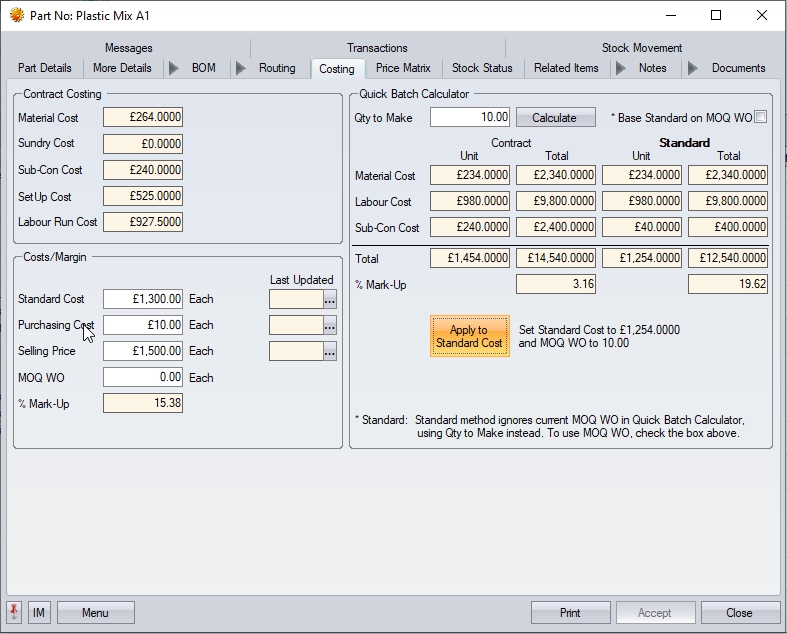
This screen calculates various cost values based on the information entered so far against BOM parts and the routing operations.
Contract Costings
The first set of costings shown are referred to as Contract Costings. These are job costings based on the exact requirements for manufacturing one unit and do not consider any minimum order quantities that are set up on any purchased or sub-assembly parts used in the manufacture of this part.
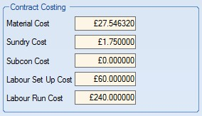
| Material Cost | This is the total cost of purchased material required to manufacture one unit of the selected part. |
| Sundry Cost | This is the total cost of sundry items required to manufacture one unit of the selected part. This is calculated from all the parts marked as sundry items on the BOM parts list. |
| Subcon Cost | This is the total cost of all sub-contract operations listed on the currently selecting routing. |
| Labour Set Up Cost | This is the cost associated with all the routing operation’s set up times based on the currently selected routing. |
| Labour Run Cost | This is the cost associated with all the routing operation’s run times based on the currently selected routing. |
Costs/Margins
This section of the screen shows the costs and margin set against the current part.
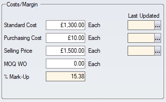
| Standard Cost | This is both a system calculated and user maintained field. For purchased items, this can be the average purchasing price. |
Example:
Part A costs £3.90 from Supplier 1 and £4.10 from Supplier 2 – the user may choose to set the standard cost for this part as 4.00
For manufactured items, this field can be populated manually by the user if a standard price is known or can be calculated using the Quick Batch Calculator on the right of this screen. This allows the user to enter a preferred quantity to manufacture. The system will then, based on information previously entered in the BOM and Routing display the Total Cost for the batch and a subsequent Cost Per Item.
If the user is happy with the calculated standard cost, they can update the Standard Cost and work order minimum order quantity (MOQ WO) fields with the values calculated using the Quick Batch Calculator by clicking on the APPLY STANDARD option.
![]()
| Purchasing Cost | This is both a system calculated and user maintained field. This is the last price paid for this item. The system will default to the last price for this item based on purchase orders entered. The user can manually update this field if they require. |
| Selling Price | This is the default selling price for the item. This is manually maintained within Progress. |
| MOQ WO | This is both a system calculated and user maintained field. This is the minimum batch quantity for which the user plans to create works orders. The user can manually type in a minimum quantity or by using the Quick Batch Calculator the system can suggest a quantity. Updating this field updates the corresponding field on the More Details section of the inventory record. |
| % Margin/Markup | This field is calculated based on how the profit margin has been configured in the system options. |
![]()
If the system has been configured to calculate the profit margin based on Mark-Up, then the calculation is as follows:
MARK-UP: (Selling Price – Standard Cost) / Selling Price
If the system has been configured to calculate the profit margin based on Margin, then the calculation is as follows:
MARGIN: (Selling Price – Standard Cost) / Standard Cost
For more information on profit, cost mark-up and cost margin options, please refer to the Costing Defaults section of the system options in the manual.
| Last Updated | These fields reflect the date that the standard, purchasing and selling values were last updated. |
| These cost/price fields can be updated in a number of ways, and will have the Last Updated date amended each time. When the user amends any of these cost/price fields, the Last Updated date will be updated accordingly. |
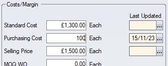
| The user also has the ability to amend the date without changing the value. This can be useful if the user has checked the prices, confirmed there is no change, and wishes to update the date to reflect that. This can be done by clicking on the option alongside the date and will set the Last Updated date to the current date. |
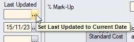
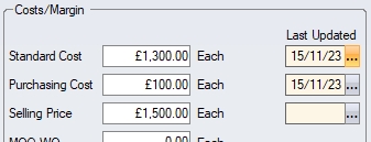
Quick Batch Calculator
The Quick Batch Calculator permits the user to estimate planned production costs for a quantity of an item.
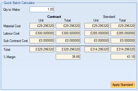
The QTY TO MAKE value will default to the MOQ WO entered by the user, although the user can change this value to any batch size they require.
After entering the desired quantity the system, based on information previously entered in the BOM and Routing screens, display the material, labour and sub-contract costs for the specified batch size. The values are given as two calculations:
| Contract | This is the costs associated with the manufacture of the specified batch quantity. This calculation does not consider minimum order quantities for either manufactured or purchased items, therefore set up costs are always divided between the batch quantity. |
| Standard | This is the costs associated with the manufacture of the specified batch quantity, including any minimum order quantities that have been set up against parts. This results in set up costs being split over minimum order quantities as opposed just the batch quantity. |
A Total Cost for the batch and a subsequent Cost Per Item will also be displayed for both costing methods above. No material or labour mark-up is included in the figures displayed. If the user is happy with the costings displayed for the batch, they can update both the MOQ WO and Standard Cost fields by clicking on the APPLY STANDARD option. The MOQ WO value will be updated to the Qty To Make value and the Standard Cost will be updated based on how the Cost Roll Up Basis option has been configured in the system options.
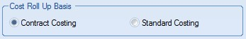
If Contract Costing is selected, the Standard Cost will update to the Unit Cost value from the Contract Costing calculation side of the Quick Batch Calculator. If Standard Costing is configured, the Standard Cost will update to the Standard Costing value from the Quick Batch Calculator.
For more information on the costing methods available within Progress, please refer to the Costings Defaults of the system options section of the manual.
Once any changes have been made to the costings screen, the user can click the ACCEPT option to save the changes made.
This section allows the user to set up price breaks for suppliers and/or customers for the current part number. The options at the top of the screen allow the user to select either Customer Price Matrix or Supplier Price Matrix. Selecting either will present the user with the current price matrix details for that category.
![]()
The screens for both the customer and supplier price matrixes are identical with the same options available to modify and save the details.
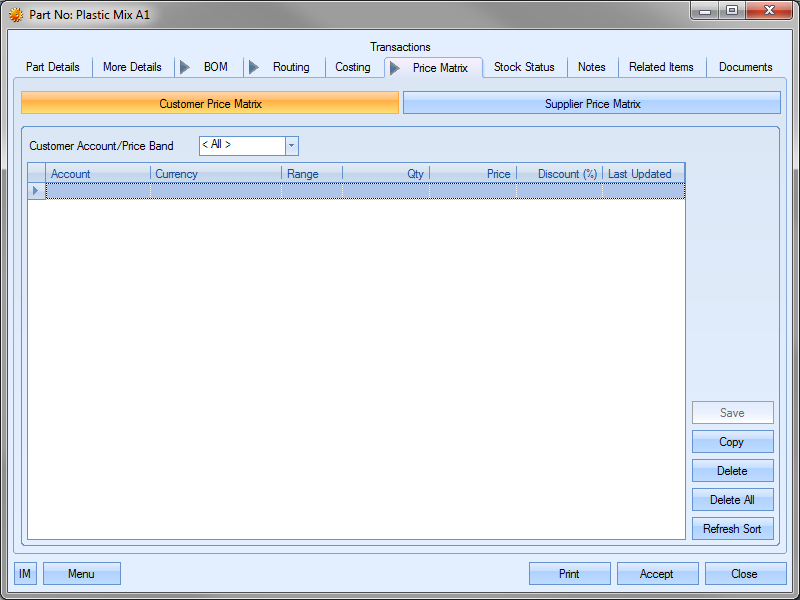
This screen allows the user to set up price breaks on three levels; against a specific customer or supplier, against a price band (group of customers or suppliers) or for all customers or suppliers.
(For the following examples, the customer price matrix has been used to demonstrate the functionality available, but the same options and methods can be applied to the supplier matrix screen.)
Adding A Customer/Supplier Specific Price Matrix
The user can add a price matrix for a specific customer or supplier by firstly choosing the customer or supplier account from the drop-down list at the top of the grid.
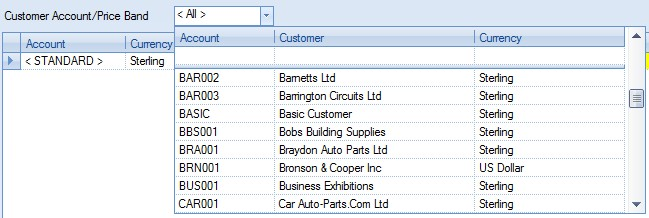
Once selected, the user can then add the price break information to the grid using the highlighted fields.
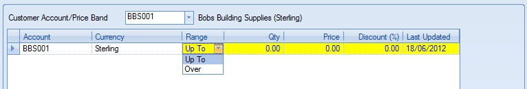
The UP TO option is inclusive of the value entered whereas the OVER option is exclusive of the value entered. The following shows some Price Matrix entries for a part for the selected customer or supplier.
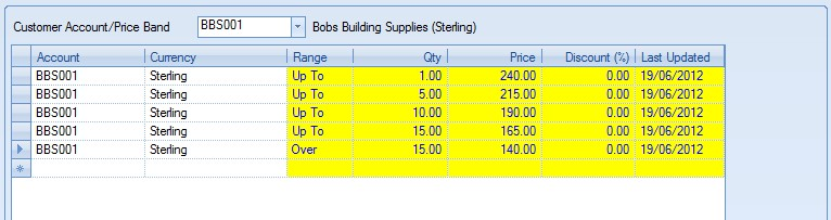
Once the details have been entered, the user can save the details by clicking on the Save option. Based on the information set up in the price matrix, the following logic would apply for this part and this customer:
Sales order quantity of 0 - 1 would have a price of £240
Sales order quantity of 2 - 5 would have a price of £215
Sales order quantity of 6 - 10 would have a price of £190
Sales order quantity of 11 - 15 would have a price of £165
Sales order quantity over 15 would have a price of £140
The price breaks entered into the Customer Price Matrix will take effect when a new sales order is created for the price matrix customer and the order quantity is entered. Price breaks entered into the Supplier Price Matrix will take effect when a new purchase order is created for the selected supplier and the quantity required is entered.
Adding A Price Band Specific Price Matrix
The user can add a price matrix for a specific price band (a group of customers or suppliers) by firstly choosing the price band from the drop-down list at the top of the grid. Price bands are listed with the “< XXX >” format.
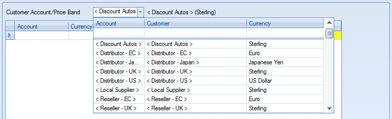
Once selected, the user can then add the price break information to the grid using the highlighted fields.
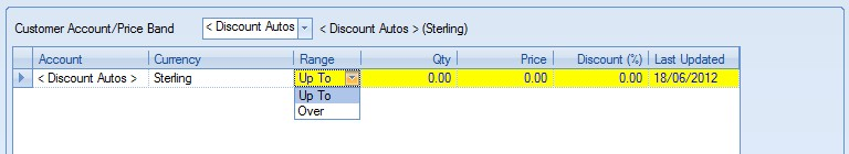
Once the details have been entered, the user can save the details by clicking on the Save option. The following shows the price matrix information as set up against a selected price band.
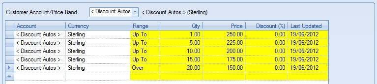
When set up against a price band, the price breaks are applied when a sales order is created for the selected part for ANY customer or supplier within that price band.
For more information on Price Bands, please refer to the List Maintenance section of the manual. For details on how to link a customer or supplier to a price band, please refer to the Customer or Supplier sections of the manual respectively.
Adding a General Price Matrix
The user can add a price matrix for all customers or suppliers for a particular part by simply adding the price breaks to the matrix without specifying an account number or price band.
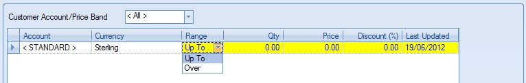
Instead of the user specifying an account or a price band, the account information defaults to “< STANDARD >”. This is the default for general customer or supplier price matrices. The user can then add all the price break information as already described above.
Once general price break information has been entered, the price breaks are applied when a sales order or purchase order is created for the selected part for ANY customer or supplier. A general customer price matrix is shown below.
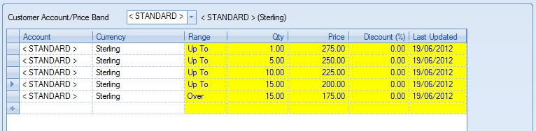
Once the details have been entered, the user can save the details by clicking on the SAVE option.
Copying An Existing Price Matrix
The user can copy an existing price matrix from another part using the COPY option.
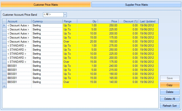
Clicking this option prompts the user to search for the part they wish to copy the price matrix from.
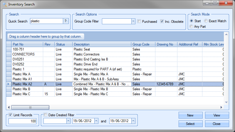
Once the part has been identified, the user can click the SELECT option to pull through the price matrix details. This will overwrite the existing price matrix details.
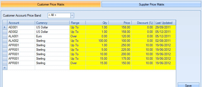
Once the user is happy with the copied price matrix details, they can save the new details using the SAVE option.
Deleting Price Matrix Details
The user can remove entries from the price matrix screen using the DELETE option.
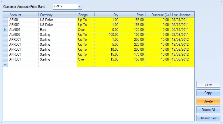
To delete an entry, the user must highlight the price matrix entry to be deleted and click on the DELETE option. The user will be prompted to confirm the deletion as follows.
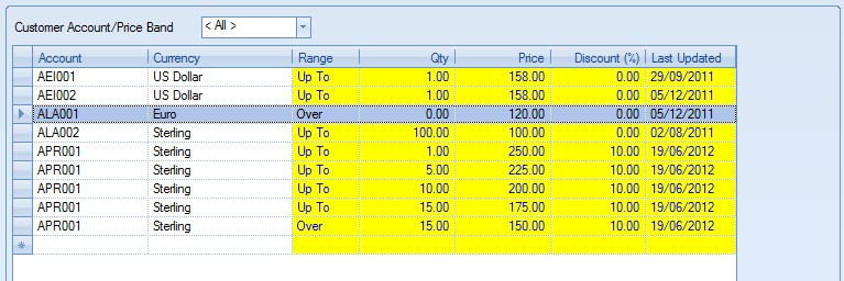
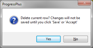
Clicking the NO option will return the user to the price matrix screen. The user can proceed with the deletion by clicking the YES option.
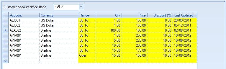
The user can then save the changes made by clicking on the SAVE option.
Deleting All Price Matrix Details
The user can clear all price matrix information from a part by using the DELETE ALL option.
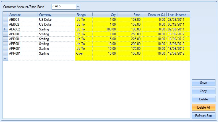
Clicking the DELETE ALL option will prompt the user to confirm the deletion.
Clicking the NO option will return the user to the price matrix screen. Clicking YES will continue with the deletion.
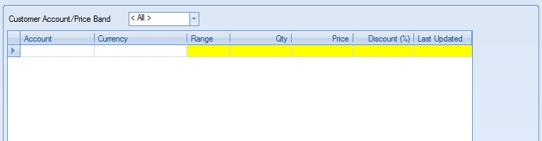
The user can then save the changes made by clicking on the SAVE option.
Refresh/Sort Price Matrix Details
If changes have been made to price matrix or if the user has changed the sort sequence of the details shown, the user can return to the default sequencing of Account, Range and Qty by clicking on the REFRESH SORT option.
Once any changes have been made to the price matrix screen, the user can click the ACCEPT option to save the changes made.
Stock Status
This screen allows the user to see detailed stock information for the selected part.
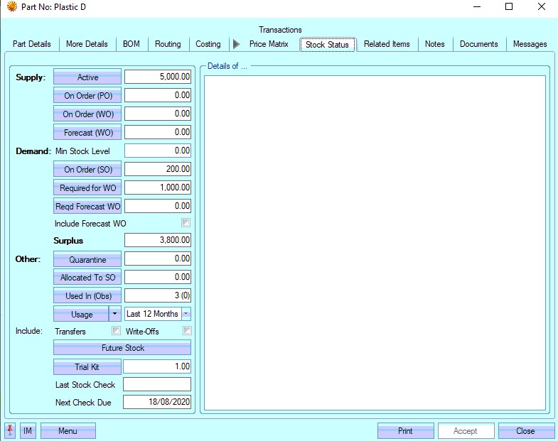
Detailed information can be viewed by clicking onto the appropriate field header on the left hand side of the screen. The figure displayed to the right of the headers is the total number relevant to the following headers.
Active
Clicking onto this option will display a list of the active (non-quarantined stock) that is currently held in the system.
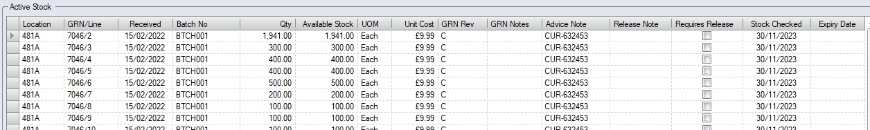
The user is presented with information as shown above. Each line of detail relates to a specific goods receipt number (GRN) along with the associated stock information as follows:
| Location | This is the current inventory stock location of this GRN/batch. |
| GRN/Line | This is the Goods Receipt Number (GRN) associated with the batch. |
Received This is the date the GRN was received.
| Batch No | This is the specific batch number for this batch. For manufactured items, this is WO and WO receipt number the batch was created from. For purchased items, this is the batch recorded on receipt from the supplier. |
| Qty | This is the current active quantity for this GRN/batch. |
Available Stock This is the current "free stock" of the batch (i.e. not currently allocated, available for immediate use, etc.)
| UOM | This is the unit of measure of the current part. |
| Unit Cost | This is the current GRN unit cost for this GRN/batch. |
| GRN Rev | This is the revision of the GRN/batch. |
| GRN Notes | These are any GRN specific notes added to the GRN, either on receipt or added to the GRN record. |
| Advice Note | This is the advice note information recorded against the GRN, either on receipt or added to the GRN record. |
| Release Note | This is the release note information recorded against the GRN, either on receipt or added to the GRN record. |
| Requires Release | This indicates whether the GRN is currently on temporary hold (i.e. "Requires Release"). |
| Stock Checked | This is the date the part was last stock checked |
The user can directly access the GRN records of any stock listed by clicking on the GRN number field on the grid.
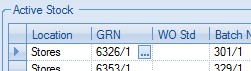
Clicking on the ![]() option opens up the GRN record for the user to view or change.
option opens up the GRN record for the user to view or change.
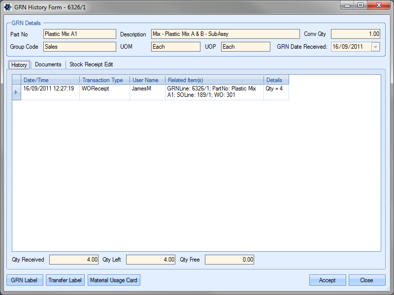
The user can return to the Stock Status screen by clicking ACCEPT or CLOSE options.
On Order (PO)
Clicking onto this option will display a list of purchase orders that have an outstanding quantity for this part.
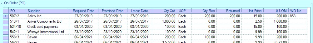
The grid shows the following information:
| PO | Purchase order number/line number |
| Supplier | The supplier from whom the goods have been ordered |
| Required Date | This is the Required Date from the associated PO line |
| Promised Date | This is the Promised Date from the associated PO line |
| Latest Date | This is the Latest Date from the associated PO line |
| Qty Ord | Quantity ordered on this purchase order number |
| UOP | Unit of purchase for this part |
| Qty Rec | Quantity of this part already received on this purchase order |
| Returned | This is the quantity that has been supplier returned on the PO line |
| Unit Price | Price per UOP for this item on this purchase order excluding VAT and other charges |
| # UOM | Equivalent unit of measure quantity |
| WO | This is the work order number associated with the PO line |
The user can directly access any purchase order listed by double-clicking on the purchase order. This will open the purchase order for the user to view or amend.
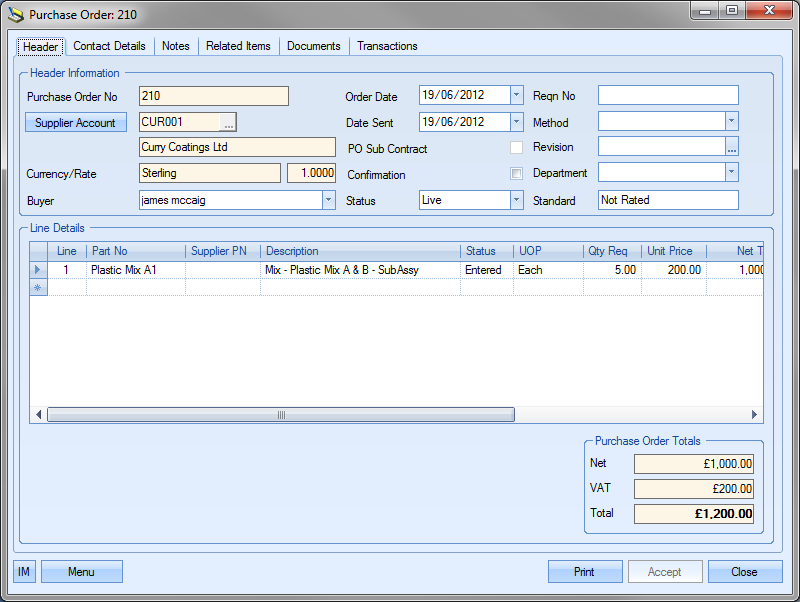
The user can return to the Stock Status screen by clicking on the ACCEPT or CLOSE options.
On Order (WO)
Clicking onto this option will display a list of works orders that are outstanding for this item, i.e. work orders currently manufacturing this part.
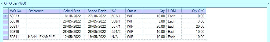
The grid shows the following information:
| WO | Works order number on which the goods are to be produced |
| Reference | Internal work order reference. For work orders created from sales order line requirements, this is the customer order number. |
| Sched Start | This is the planned start date for this works order |
| Sched Finish | This is the planned finished date for this works order |
| SO | The sales order this works order is for. If work order is not linked to a sales order, this shows as N/A |
| Status | The current status of the works order |
| Qty | The quantity of the item that is required on that works order number |
| UOM | The unit of measure of the part on the work order |
| Qty O/S | The quantity of this item still outstanding on the works order |
The user can directly access any work orders listed by double-clicking on the work order. This will open the work order for the user to view or amend.
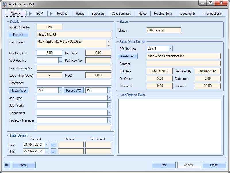
The user can return to the Stock Status screen by clicking on the ACCEPT or CLOSE options.
Forecast (WO)
Clicking on this option lists all the forecast work orders created for the selected part.
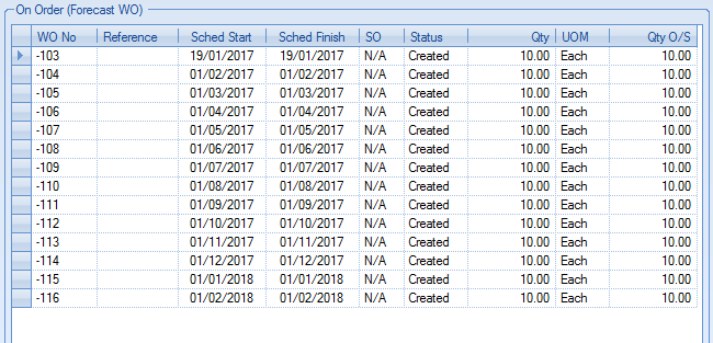
The grid shows the following information:
| WO No | This is the forecast works order number. |
| Reference | This is the reference text recorded against the forecast works order. |
| Sched Start | This is the forecast works order's planned start date. |
| Sched Finish | This is the forecast works order's planned finish date. |
| SO | This is the sales order number associated with the forecast works order. |
| Status | This is the current status of the forecast works order. |
| Qty | This is the quantity on the forecast works order. |
| UOM | This is the unit of measure of the forecast works order. |
| Qty O/S | This is the outstanding quantity on the forecast works order. |
Min. Stock Level
This is the part's minimum stock level as set in the More Details tab of the part number. The minimum stock level (MSL) is considered part of the demand for a part to maintain the desired quantity in stock.
On Order (SO)
Clicking onto this option will display a list of sales orders that have an outstanding requirement for this item.
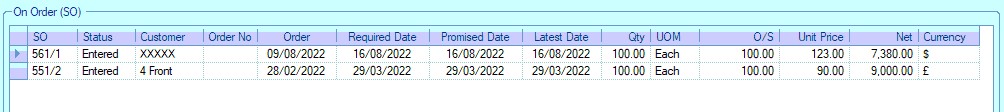
The grid shows the following information:
| SO | Sales order number/line number |
| Status | Current sales order line status |
| Customer | The sales order customer |
| Order No | The customer’s order number or reference |
| Order | Sales order creation date |
| Required Date | Sales order line Required Date |
| Promised Date | Sales order line Promised Date |
| Latest Date | Sales order line Latest Date |
| Qty | Sales order line quantity |
| UOM | Part's unit of measure |
| O/S | Outstanding quantity still to be delivered |
| Unit Price | Sales order line unit price |
| Net | Total NET value of this sales order line |
| Currency | Customer currency |
The user can directly access any sales orders listed by double-clicking on the sales order. This will open the sales order for the user to view or amend.
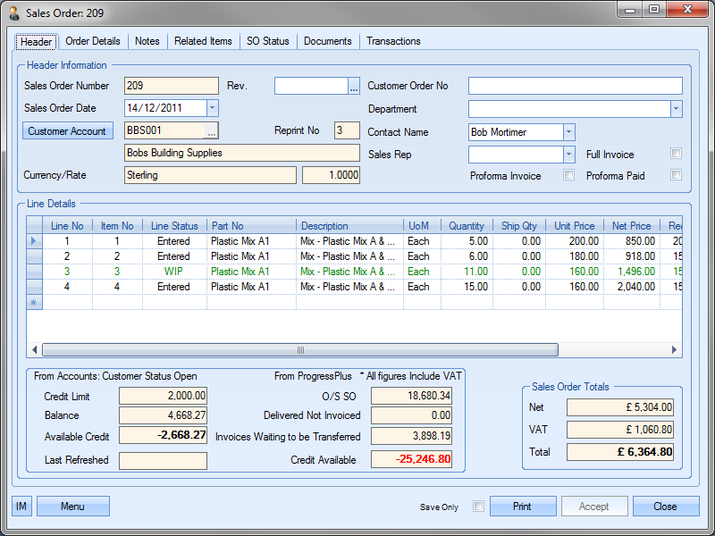
If the system is configured to exclude on hold SO lines and/or Unpaid Proforma SOs from the ON ORDER (SO) total, then the system will show any quantities that are unpaid proforma and/or on hold in brackets against the ON ORDER (SO) total. The ON ORDER (SO) grid will also group the SO lines accordingly as shown below.
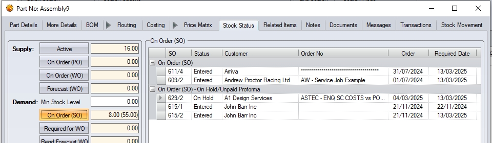
Required for WO
Clicking onto this option will display a list of outstanding works orders that require the selected part i.e. work orders where the current part is a component part.
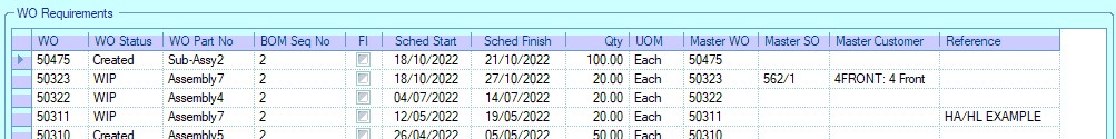
The grid shows the following work order information:
| WO | Work order number |
| WO Status | Current work order status |
| WO Part No | Part being manufactured on work order |
| BOM Sequence No | Sequence number of current part on work order BOM |
| FI | Indicates whether the part is a "free issue" part on the associated work order BOM |
| Sched Start | Scheduled work order start date |
| Sched Finish | Scheduled work order finish date |
| Qty | Work order quantity |
| UOM | Work order part unit of measure |
| Master WO | This is the associated Master work order (top-level assembly) |
| Master SO | This is the associated sales order linked to the Master work order |
| Master Customer | This is the customer of the associated Master sales order |
| Reference | This is the associated work order reference (typically the customer order number if work order generated from SO requirements) |
The user can directly access any work orders listed by double-clicking on the work order. This will open the work order for the user to view or amend.
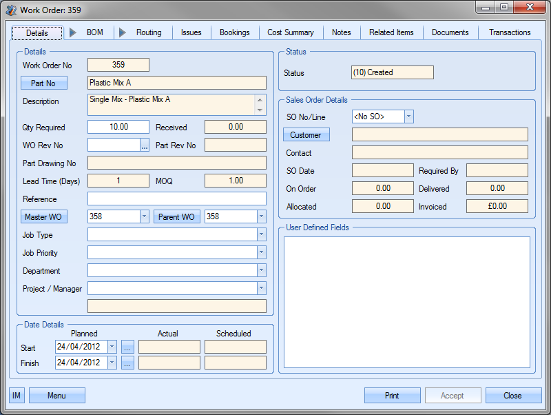
The user can return to the Stock Status screen by clicking the ACCEPT or CLOSE option.
Reqd Forecast WO
Clicking this option will display a list of forecast WOs which require the current part.

The grid shows the following information:
| WO | This is the forecast works order number. |
| WO Status | This is the current status of the work order. |
| WO Part No | This is the part number the requirement is for. |
| BOM Seq No | This is the selected part's sequence number on the parent part's BOM. |
| FI | Indicates whether the part is a "free issue" on the associated work order BOM |
| Sched Start | This is the forecast works order's planned start date. |
| Sched Finish | This is the forecast works order's planned finish date. |
| Qty | This is the quantity required for the associated forecast works order. |
| UOM | This is the unit of measure of the selected part. |
| Master WO | This is the master works order number for the forecast works order. |
Surplus / Shortage
At the bottom of the form a message will be displayed showing any stock shortage or surplus.
![]()
![]()
This is a system maintained figure based on the following calculation
Active + On Order (PO) + On Order (WO) – On Order (SO) – Req for WO – Minimum Stock Level
Figures less than zero indicate there is a shortage and that further stock is required to meet current requirements. Figures greater than zero indicate there is a surplus and that no additional stock is required to meet current requirements.
The user also has the option of including forecast works orders in the shortage/surplus calculation. Ticking the option shown below will adjust the calculation to take them into account as part of the supply.
![]()
Quarantine Stock
Clicking onto this option will display a list of the quarantined (non-active) that is currently held in the system.
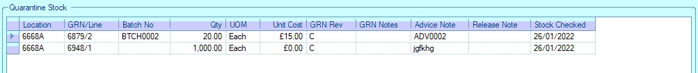
The grid shows the same information as the Active stock grid but will only show inventory stock locations marked as “Quarantine” locations. Again, the user has the ability to directly access the GRN records shown by clicking on the ![]() option against the GRN number.
option against the GRN number.
Allocated to SO
Clicking onto this option will display a list of sales orders that have a quantity of the selected part currently allocated to them. This screen is available to all users including those who do not have access to sales orders. If the user does not have costing access rights the GRN cost will be hidden.
The user will get the below message when they try to access sales orders if they do not have sales order access rights.

The grid shows the following information:
| SO | The sales order number/line number |
| GRN/Line | The GRN number of the batch currently allocated to the sales order |
| Batch No | The batch number of the stock currently allocated to the sales order |
| Qty | Quantity currently allocated |
| UOM | Part unit of measure |
| Location | Current stock location of allocated GRN |
| Unit Cost | Unit cost of the GRN allocated |
| Customer | Sales order customer |
| Required Date | Required date from the associated sales order line |
| Promised Date | Promised Date from the associated sales order line |
| Latest Date | Latest Date from the associated sales order line |
The user can directly access any sales orders listed by double-clicking on the sales order. This will open the sales order for the user to view or amend.
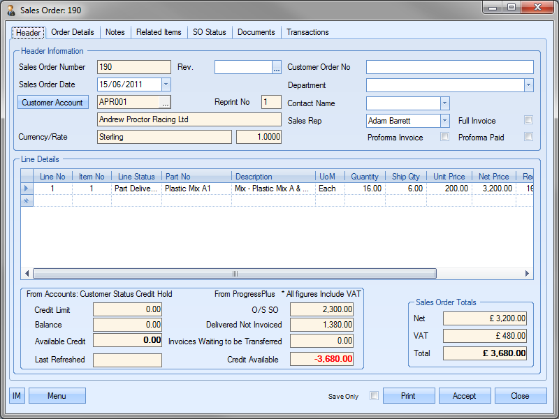
The user can return to the Stock Status screen by clicking the ACCEPT or CLOSE option.
Used In (Obs)
This option lists all manufactured parts where the current part is a component. The figure in brackets indicates the number of these parts which are obsolete. The grid displayed when the user clicks on this option lists all parts where the current part is a component. Any obsolete parts are highlighted in red.
![]()
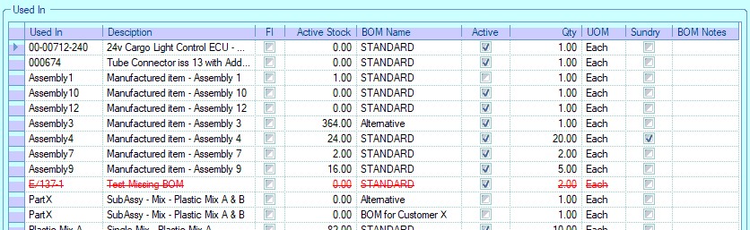
![]()
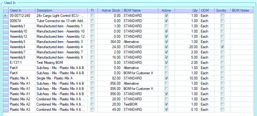
The user can see from the grid which assembly parts the current part is used in, the associated BOM name, the current assembly part status as well as the current active stock of the assembly part and whether the current part is a "free issue" part (FI) or a sundry item. BOM notes are also displayed for information purposes.
Stock Usage
This option allows the user to see details of the parts usage over a specified period. The user can select a number of date ranges for analysis with the details and chart showing on the right.
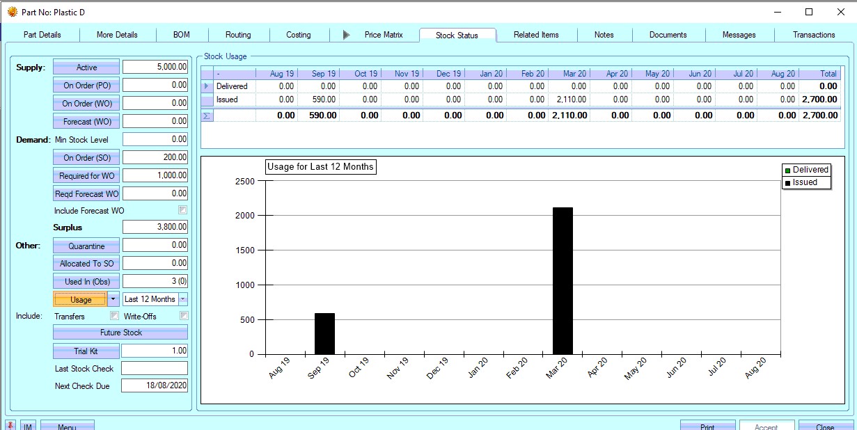
The user also has options to include write off and transfer transactions in the usage figures. By default, these are not included but can be by simply clicking on the options shown below.
![]()
The user can also generate a Stock Transaction report by clicking the drop-down option shown below. This will generate a report giving a list of all transactions for the current part over the specified date range.
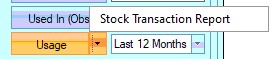
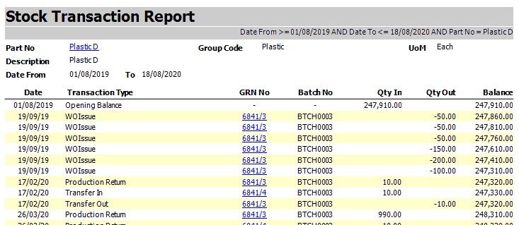
Future Stock
This option shows all future transaction of stock for the current part. The screen shows an opening balance of stock for the current date and then lists all stock transactions due for this part as well as an overall stock value based on the transactions listed.
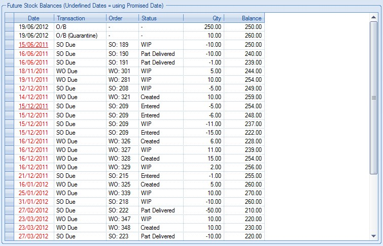
The information in the grid is as follows:
| Date | This is the planned transaction date. Dates shown in black indicate current or future dates. Dates highlighted in red are past-due dates. All sales order and purchase order dates are based on the LATEST DATE of the line item. |
| Transaction | This specifies the type of transaction. Examples shown in the screenshot above are: |
| WO Due: Date work order is due for completion |
| SO Due: Date sales order is due to be delivered |
| PO Due: Date purchase order is due to be received |
| O/B: Opening balance |
| O/B (Quarantine): Opening quarantine balance |
| Order | This is the order type and number relating to the transaction |
| Status | This is the current order status |
| Qty | This is the planned transaction quantity. For sales orders this will be the so line qty. For work orders, this will be the work order quantity and for purchase orders this will be the purchase order line qty. |
| Balance | This is the future stock figure. This calculated from the opening balance quantity and all subsequent transactions listed, either adding or subtracting stock based on the transaction type. The final balance shown against the last listed transaction should match the Surplus/Shortage figure shown in the Stock Status screen. |
Trial Kit
This option allows the user to generate a report for a potential work order based on a quantity specified by the user. By default, the trial kit quantity is the work order minimum order quantity (WO MOQ).
![]()
The user can amend the quantity for the trial kit by changing the quantity shown in the box next to this option. Once the desired quantity has been entered, the user can click the TRIAL KIT option. This will present the user with two options: Flat BOM and Exploded BOM. #
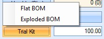
The Flat BOM option presents the user with the following report:
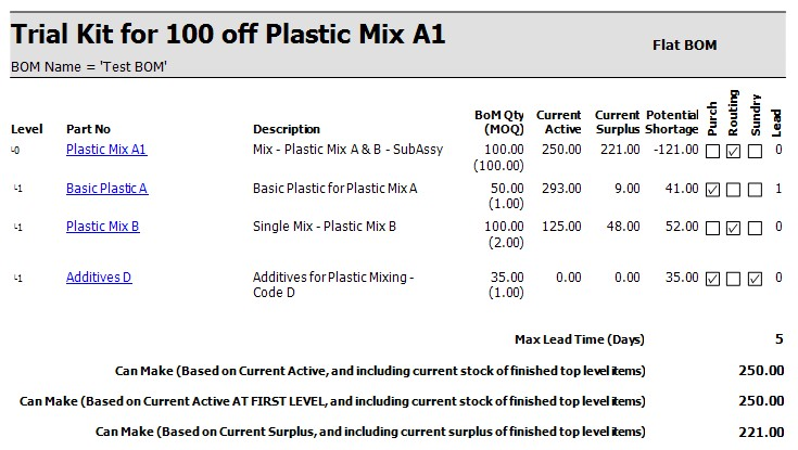
This flat BOM report shows the current part and its immediate sub-components. The Exploded BOM option presents the user with the following report:
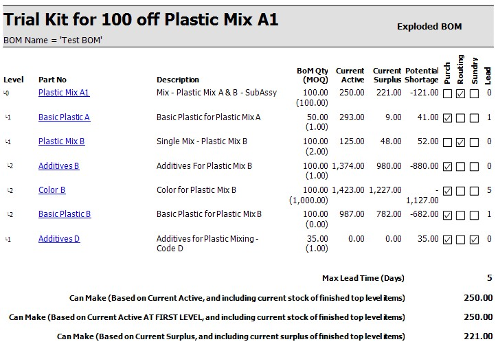
The exploded BOM report shows the full bill of materials for the current part, including all its sub-assemblies and their component parts. Both reports show the BOM requirements, the current active stock, the surplus based on the current active stock and any potential shortages that might be incurred. The part figures shown are as follows:
| BOM Qty (MOQ) | Total requirement based on the trail kit quantity. MOQ for the part is shown in brackets. For purchased parts, this is the PO MOQ, for manufactured parts, it’s the WO MOQ. |
| Current Active | Total current active stock of the part (from stock status) |
| Current Surplus | Total current surplus stock of the part (from stock status) |
| Potential Shortage | Calculated as the difference between the current surplus and the BOM quantity required. Negative values indicate no shortages (a surplus) where as positive values indicate shortages |
| Lead | Lead time of part. For purchased parts, this is the purchasing lead time, for the manufactured parts, it’s the manufacturing lead time. |
The summarised values at the bottom of the report show the following:
- Max Lead Time (days)
- Can Make (Based on current active, and including current stock of finished top level items)
- Can Make (Based on current active AT FIRST LEVEL, and including current stock of finished top level items)
- Can Make (Based on current surplus, and including current surplus of finished top level items)
Highest lead time of all the BOM component parts
This is the total number available based on the current ACTIVE stock of all BOM component parts (including sub-level components) AND the total ACTIVE stock of the finished product.
This is the total number available based on the current ACTIVE stock of all immediate BOM component parts AND the total ACTIVE stock of the finished product.
This is the total number available based on the current SURPLUS stock of all BOM component parts (including sub-level components) AND the total SURPLUS stock of the finished product.
Last Stock Check/Next Check Due
These fields show the dates of the last and next stock check.
The last stock check date is populated when the system is updated only via the stock import process after a stock take has been done while the next check due field is populated based on the part's stock category which calculates the next check date based on the period set against the stock category.
Notes
This section allows the user to enter both general and specific notes and warnings against the current part.
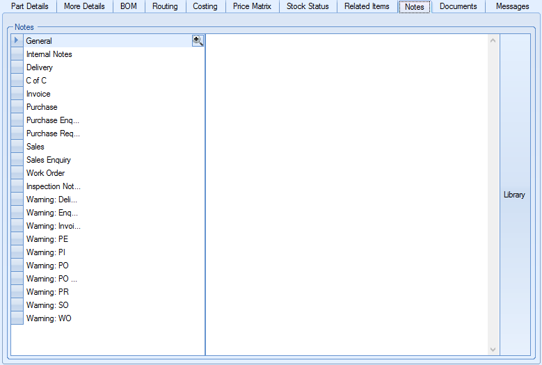
The user can select any of the categories on the left hand side before entering any text they wish on the right hand side of the screen. Once a note has been added to a particular category, the category is highlighted in bold on the left with a part of the note displayed too.
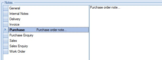
The user also has the option of adding notes from the Notes Library within Progress. This can be done by clicking on the LIBRARY option on the right hand side of the screen. This presents the user with the following screen.
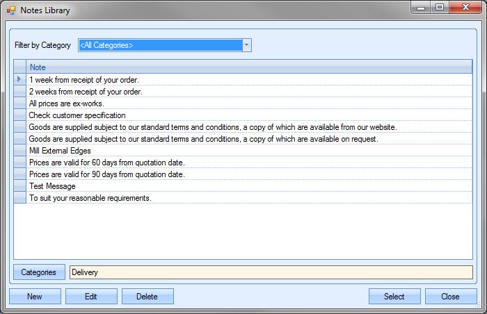
The user can then search or filter the notes listed to find the one required. Once located, the user can transfer the note back to the part notes screen by highlighting the note and clicking the SELECT option. This will pull the selected note through to the current section of the part notes.
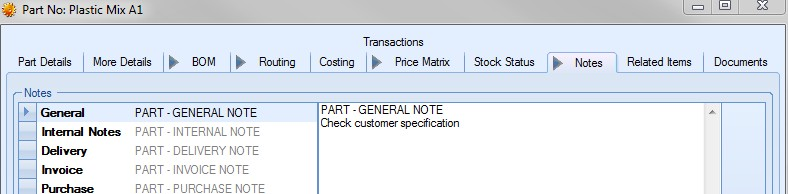
Most of the notes entered on this screen are designed to copy through to the relevant sections of Progress. Each notes category indicates the section of Progress that the note is designed to appear in when the part appears in those sections. The following details where the notes appear in the different sections of Progress.
| General | These notes are held only against the part record. These are not duplicated to any other section of Progress, are printed on the Inventory Detail report for the part. |
| Internal Notes | These notes are held only against the part record. These are not duplicated to any other section of Progress and are primarily for internal use. |
| Delivery | These notes are duplicated through to the EXTERNAL NOTES of the delivery line details screen. |
| CofC | These notes are duplicated through to the INVENTORY note on the CofC details section of the delivery.. |
| Invoice | These notes are duplicated through to the EXTERNAL NOTES of the invoice line details screen. |
| Purchase | These notes are duplicated through to the EXTERNAL NOTES of the purchase order line details screen. |
| Purchase Enquiry | These notes are duplicated through to the EXTERNAL NOTES of the purchase enquiry line details screen. |
| Purchase Requisition | These notes are duplicated through to the EXTERNAL NOTES of the purchase requisition line details screen. |
| Sales | These notes are duplicated through to the EXTERNAL NOTES of the sales order line details screen. |
| Sales Enquiry | These notes are duplicated through to the EXTERNAL NOTES of the sales enquiry line details screen. |
| Work Order | These notes are duplicated through to the GENERAL NOTES of the work order screen. |
| Inspection Note | These notes are copied through to the INTERNAL NOTES of a PO line. |
| WARNING: Delivery | This text is displayed as a warning when the part is added to a delivery. |
| WARNING: Enquiry | This text is displayed as a warning when the part is added to a enquiry. |
| WARNING:Invoice/Credit | This text is displayed as a warning when the part is added to a invoice. |
| WARNING: Issue To Production | This text is displayed when the part is issued to a work order. |
| WARNING: PE | This text is displayed as a warning when the part is added to a purchase enquiry. |
| WARNING: PI | This text is displayed as a warning when the part is added to a purchase invoice. |
| WARNING: PO | This text is displayed as a warning when the part is added to a purchase order. |
| WARNING: PO Receipt | This text is displayed as a warning when the part is receipted on a PO. |
| WARNING: FI Receipt | This text is displayed as a warning when the part is receipted via a free issue receipt. |
| WARNING: PR | This text is displayed as a warning when the part is added to a purchase requisition. |
| WARNING: SO | This text is displayed as a warning when the part is added to a sales order. |
| WARNING: WO | This text is displayed as a warning when a work order is created for the part.. |
| WARNING: WO Receipt | This text is displayed as a warning when the part is receipted via a work order. |
Once any changes have been made to the notes screen, the user can click the ACCEPT option to save the changes made.
Related Items
This option shows all the related items within Progress which reference the current part.
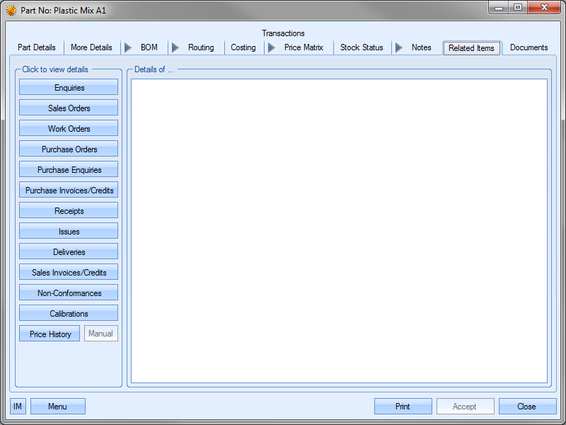
Each of the options on the left hand side will show the related relevant orders/items for the current part. Some examples are shown below.
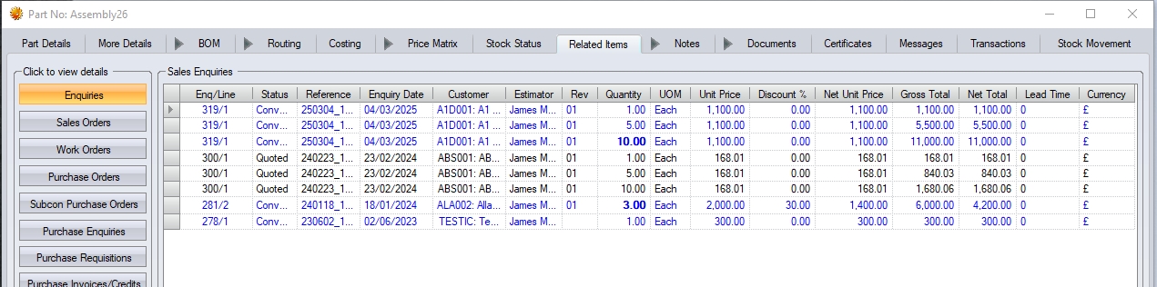
(Enquiry details)
NOTE: Where multiple quantities have been quoted on the same enquiry line (i.e. due price breaks), the system will display each quoted quantity against the enquiry line and will highlight the quantity that was converted to a sales order in bold. An example of this can be seen in the screenshot above - enquiry 319/1. Of the three quantities quoted (1, 5 and 10) it was the quantity of 10 that was converted to the associated SO, so the 10 is shown in bold.
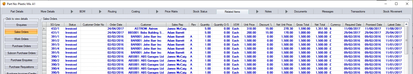
(Sales Order details)
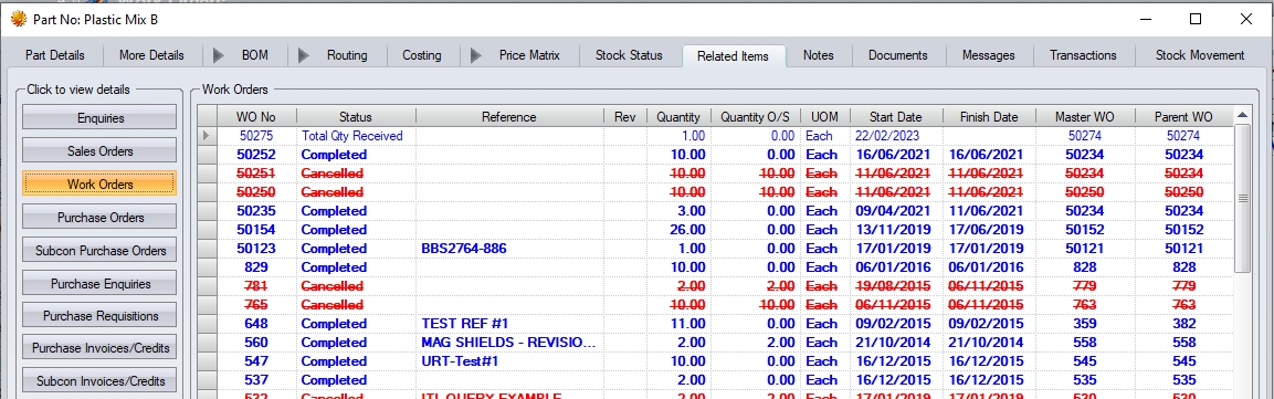
(Work Order details)
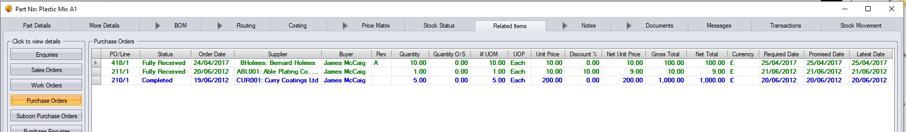
(Purchase Order details)
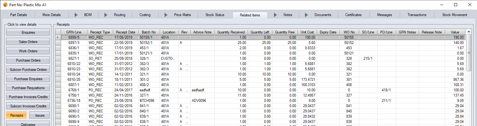
(Receipts details)
The user can access any orders, etc. listed on these screens by double-clicking on the order listed in the grid.
GRN History
Any of the screens which display a GRN number allow the user to view the GRN details by clicking on the ![]() option that appears alongside the GRN number.
option that appears alongside the GRN number.
This will present the user with GRN History screen for the selected GRN number. The user can then view or amend as necessary.
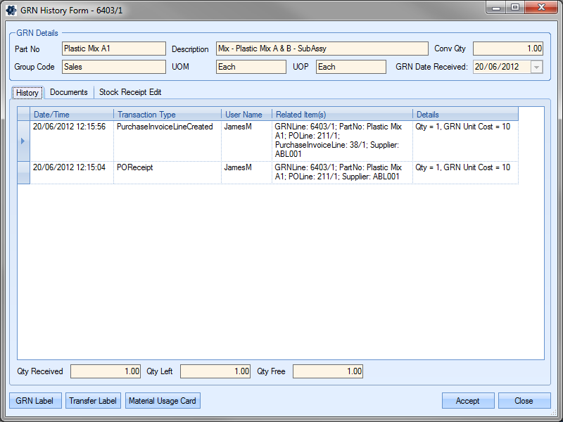
Clicking the ACCEPT or CLOSE option will return the user to the parts' Related Items screen.
Issue History
On the Issues screen, the user can also look at the issue history of a particular issue transaction by clicking on the ![]() option against the issue number. This presents the user with the following screen.
option against the issue number. This presents the user with the following screen.
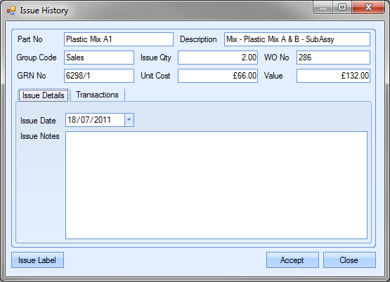
This screen displays all the details for the specific transaction selected. The user has the option of changing the issue date on this screen and to also add any notes to the transaction. Also available in the Issue History screen is a list of all the transactions made against the GRN referred to in the issue transaction. The user can view this information by clicking on the Transactions tab..
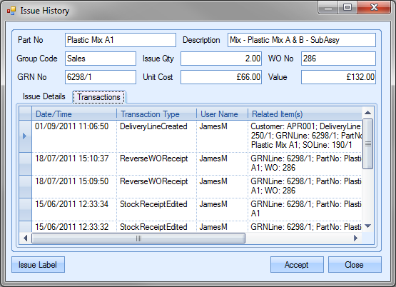
The print option at the bottom left of the screen allows the user to print a label or form for the transaction type. Not all transaction types will have this option available, but those that do will print the following:
| Material Issue to WO (WOIssue) | Prints the Issue To Production label |
| Supplier Return (SUPP_RET) | Generates supplier return note |
The user can return to the part Related Items screen by clicking on the ACCEPT or CLOSE options.
Price History
This option allows the user to view the price history for the part. This shows all the prices for all instances of the part throughout the system
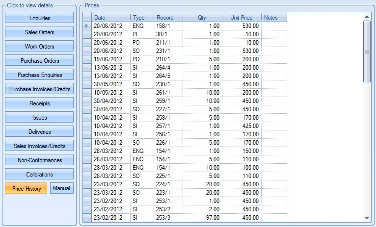
The screen shows the following:
| Date | Creation date of the associated record |
| Type | The abbreviated record type, e.g. ENQ for enquiries, PI for purchase invoices, SO for sales orders, PO for purchase orders, etc. |
| Record | This is the order number/line for the associated record type |
| Qty | Quantity associated with the record |
| Unit Price | This is the unit price used in the associated record |
| Notes | This shows any notes that have been added to the Price History record |
The user can add notes to any of the price history records by double-clicking on the required price history record. This presents the user with the following screen:
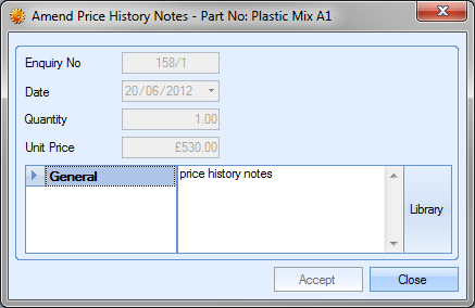
Once the user has added notes, they can click the ACCEPT option to save the notes. These are then displayed on the Price History grid.
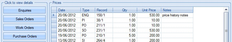
The user also has the option to add manual entries to the Price History. This allows notes to be recorded in relation to the pricing. For example, a change in a part’s selling price on the inventory record. To add these manual entries, the user can click the MANUAL option. This will present the following screen:
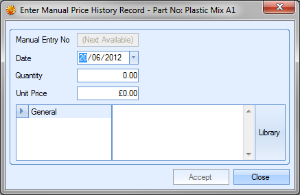
The user can complete the details of the manual price note. Once all the information has been added, the user can click the ACCEPT option to save the details. The manual entry will then appear on the Price History grid as follows:
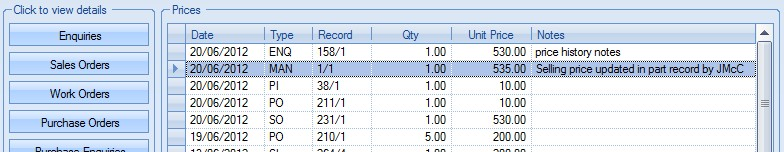
Documents
This section allows the user to attach any part-related documents. This can be correspondence emails, drawings, specification or anything else related to the part.
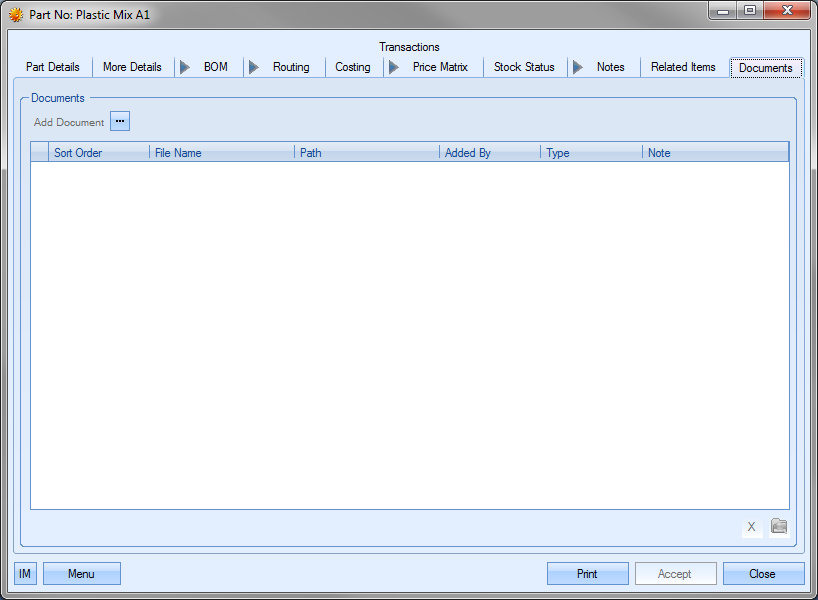
To add a document, the user clicks the ADD DOCUMENT option,![]() , and then locates the file they wish to add.
, and then locates the file they wish to add.
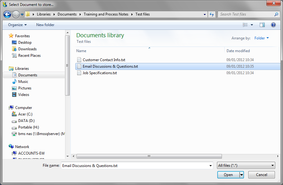
Once the required document has been selected, it will be listed in the Documents screen with any others that have been added.
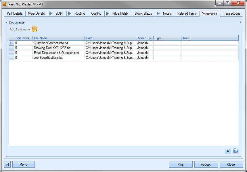
NOTE: To allow access for other users to the files added to the part record, the user must ensure that these files are held in a folder accessible by all users. Typically a shared network folder would be created for this purpose.
Once the file(s) have been specified, the user can specify a file type or comment associated with the document. The TYPE can be chosen from the drop-down list.
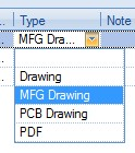
This drop-down list can be populated from the List Maintenance section of Progress in the Document Types list as shown in the screen below.
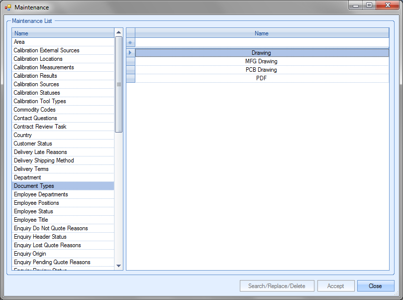
For more information on maintaining lists and the List Maintenance section of Progress, please refer to the List Maintenance section of this manual.
A note for the document can be added directly to the NOTE field as shown.
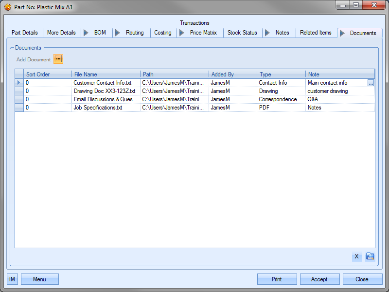
Once all documents and details have been added, the user can save the changes by clicking on the ACCEPT option.
Documents added to this screen can also be hidden from view in SFDC's Associated Documents section. The HIDE IN SFDC option against the document allows the user to stop the document being viewed within SFDC. This is often used where the document may contain sensitive or cost/pricing related information that they do not want the employee to see.
A similar option is also available on the inventory routings operations Documents Tab and also the Work Orders Document tab, again, to allow specific documents to be restricted from view.
NOTE: These options is only available if the SFDC module is active in the system. If this module has not been purchased, then this option will not be displayed.
Certificates
This tab allows the user to set default certificate requirements for the part when ordering the part from a supplier.
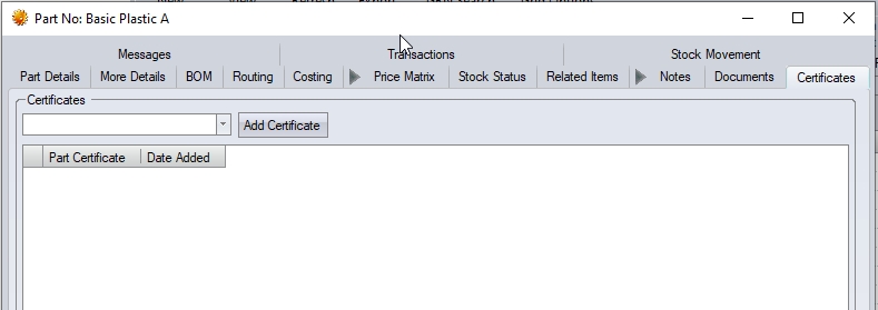
The user can use the drop-down list at the top to select the relevant certification required for the part.
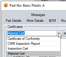
Clicking the ADD CERTIFICATE option will add the selected certificate to the part. The user can repeat this process until all the required certificates are set against the part.
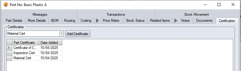
When a PO is created, and the part is added to the PO, the part's certificates will automatically be added to the PO (as shown below).
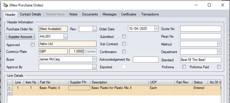
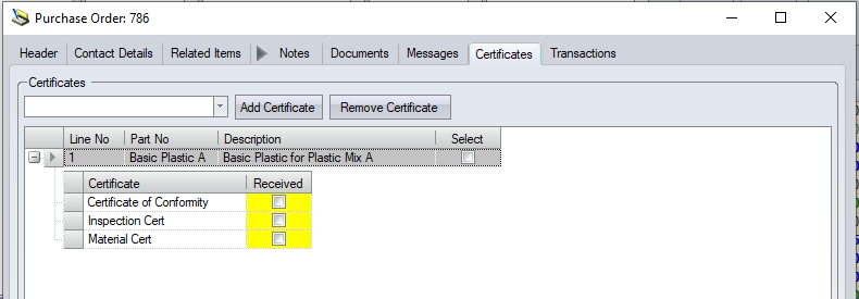
This section shows all associated messages and emails relating to the part.
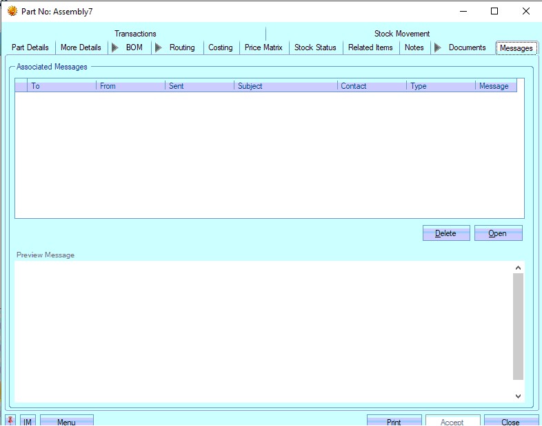
Any communication relating to the part (i.e. emails, instant messages, etc.) will all be listed here for the user to view.
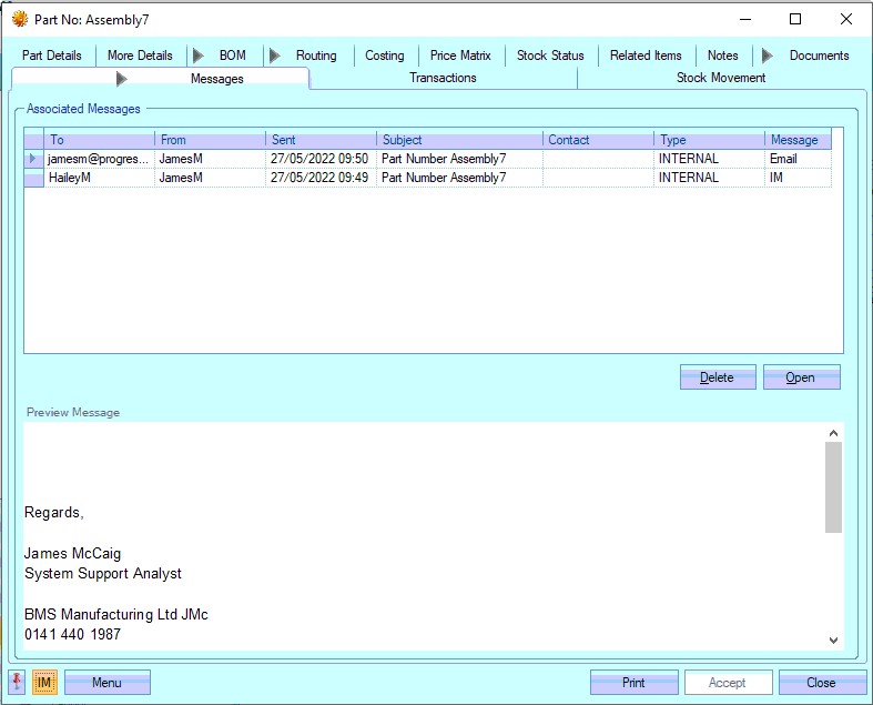
The user can open any of the items listed on this screen but either double-clicking on the listed item or by highlighting and clicking OPEN. The selected item will then be displayed for the user to view.
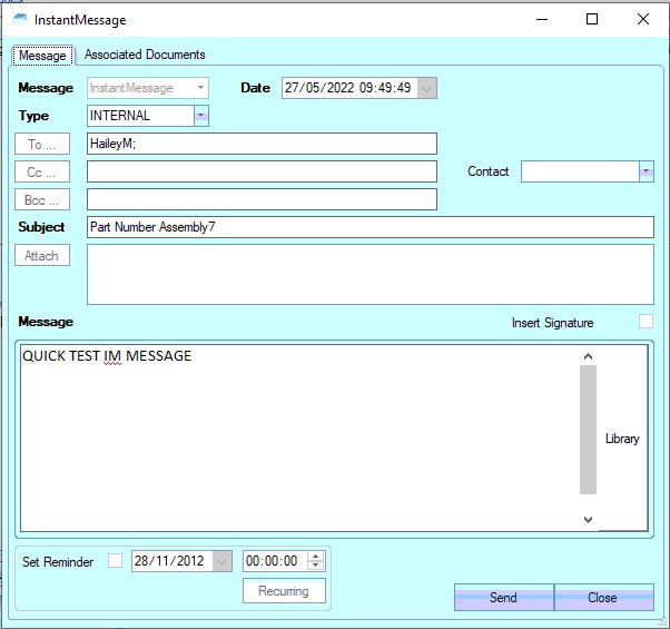
The user also has the ability remove messages recorded, if permitted. Permission to delete messages is set up against the user permissions. For more information on user permissions, please refer to the Administrator Functions > Access section of the manual. If the user has permission to remove messages, then the DELETE option will be available.
Messages can be deleted by simply highlighting the item and clicking the DELETE option. The user will be prompted to confirm the deletion.
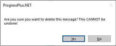
Clicking YES will delete the selected message, and the screen will be updated.
Transactions
This section shows all transactions that have been made against the part.
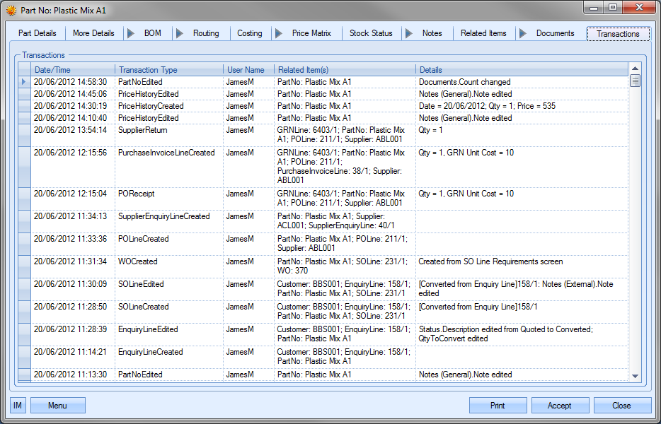
The user can see what transactions have occurred as well as details on the changes made. This is often very useful when trying to find out why something has changed unexpectedly or if the user needs to find out who made a particular change.
| Date/Time: | The date and time that the transaction occurred. |
| Transaction Type: | This field names the type of transaction recorded. This references both the area of Progress and the action, i.e. PartNoEdited – change made to a part record, EnquiryLineCreated – new enquiry line created for this part, etc. |
| User Name: | User who made the transaction. |
| Related Item(s): | Reference information on the exact data that was amended, i.e. tool number, etc |
| Details: | Brief explanation of edited information. |
Stock Movement
This tab within the part record allows the user to see the movement of the part's stock, with date filter options to look at the historical stock movements.
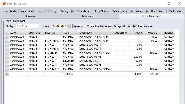
The user can select the period they wish to look at, or set a specific date to be used. This will then display all the stock movements for the part within the specified period.
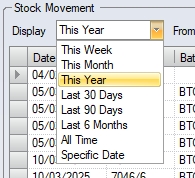
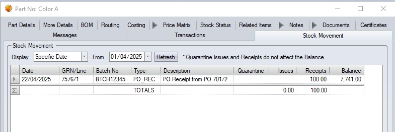
Additional Menu Options
The user has some additional options available to them when viewing a part. These options are accessible via the Menu option.
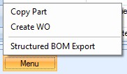
Copy Part
This option allows the user to copy the details of an existing part. This can be useful when setting up parts that are similar or even replacements for an existing part. When the user selects this option, they are presented with the following screen.
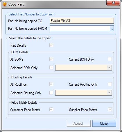
From here, the user can select the existing part they want to copy. To do this, they user must click on the ![]() option at the end of the PART NO BEING COPIED FROM field. This will present the user with the Inventory Search screen. They can use this to locate the part number required.
option at the end of the PART NO BEING COPIED FROM field. This will present the user with the Inventory Search screen. They can use this to locate the part number required.
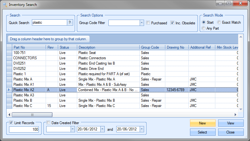
Once located, the user can highlight and click the SELECT option to return to the Copy screen with the part they wish to copy.
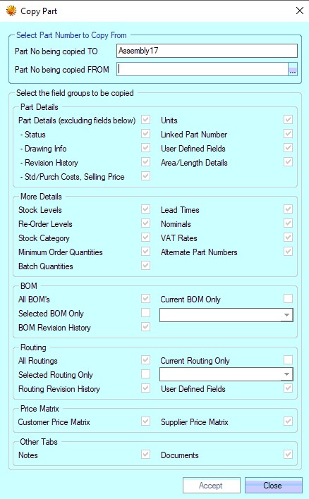
This then presents the user with the option to choose the details they wish to copy from their selected part. The options are broken down into the relevant part record sections (i.e. part details, more details, BOMs, etc.) The user can select the relevant information that's to be copied across to the new part by ticking/un-ticking the options available.
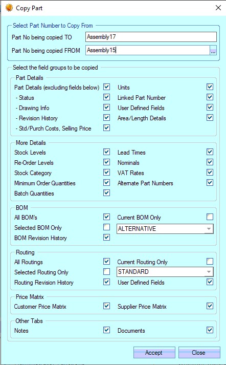
Once the user has chosen the options required, they can click ACCEPT to copy the details to the current part. The user will be prompted to confirm.
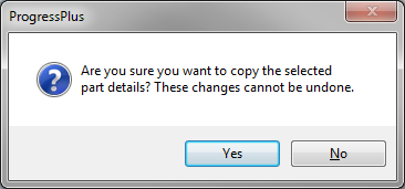
Clicking NO will return the user to the Copy Part screen. Clicking Yes will proceed to copy the details to the current part. The user can make any further amendments if necessary or click ACCEPT to save the part.
Create WO
This option allows the user to generate a work order for the selected part. Clicking this option presents the user with a new work order screen with all the details completed from the part record. The user can amend the details if necessary and save the work order using the ACCEPT option. For more information on creating and amending work orders, please refer to the Work Order section of this manual.
Create PO
This option allows the user to generate a purchase order for the selected part. Clicking this option presents the user with a new purchase order screen with all the details completed from the part record. The user can amend the details if necessary and save the purchase order using the ACCEPT option. For more information on creating and amending purchase orders, please refer to the Purchasing section of this manual.
Structured BOM Export
This option allows the user to export the part BOM for a specified quantity to an Excel spreadsheet for further analysis. Selecting this option presents the user with the following screen.
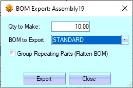
The user can enter the quantity required and choose the part BOM to export. Once selected, the user can click the EXPORT option. The user will be prompted to save the spreadsheet.
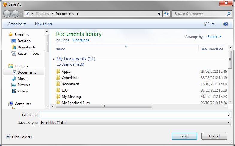
Once saved, the spreadsheet will be opened automatically for the user. An example is shown below.
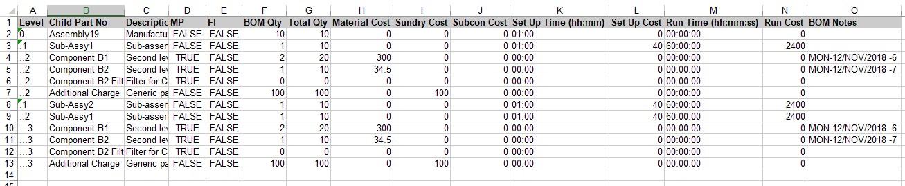
The user also has an option to consolidate common parts on the export. This is done by clicking the XXX option.
![]()
Exporting with this option applied results in a flattened BOM list, consolidating all PNs to show the total requirement through the entire BOM.
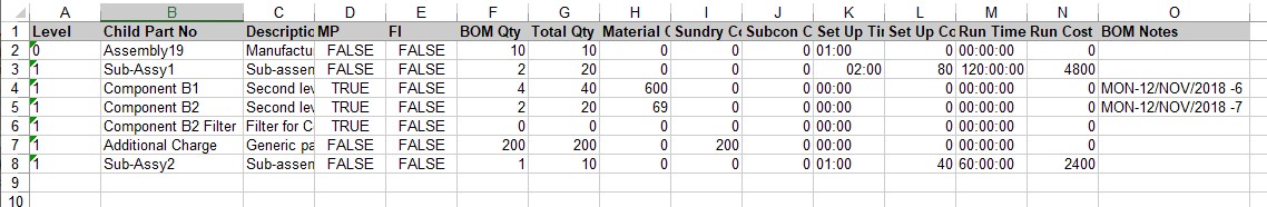
Print (Inventory Detail Report)
The PRINT option generates the Inventory Detail report. This is a summary report of the current part and its current BOM and routing. An example is shown below.
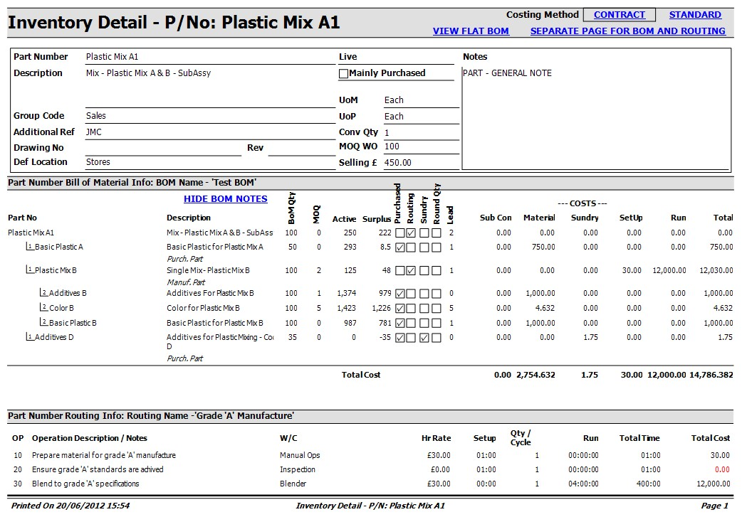
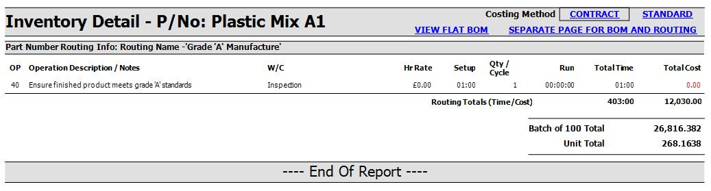
The text in blue offers the user options on how the information is generated on the report. The user can choose to view the costings based on contract or standard costing, show or hide BOM notes, view the BOM as a flat BOM or an exploded BOM or can separate out the BOM and routing information to separate pages if required.